
Polishing device for engine piston insert ring machining

A polishing device and engine technology, applied in grinding/polishing safety devices, metal processing equipment, machine tools with surface polishing, etc., can solve problems such as troublesome grinding of piston inserts, avoid dust flying, ensure cleanliness, and facilitate use. Effect

Inactive Publication Date: 2019-10-18
SHIYAN TONGLU IND
View PDF0 Cites 2 Cited by
  • Summary
  • Abstract
  • Description
  • Claims
  • Application Information

AI Technical Summary

Problems solved by technology

[0003] At present, most of the existing polishing devices for engine piston inserts on the market have the following deficiencies in the process of use: it is troublesome to polish the inner and outer rings of the piston inserts. In summary, most of the existing engine piston inserts The polishing device for ring processing does not meet the actual needs well

Method used


Image

  • Polishing device for engine piston insert ring machining
  • Polishing device for engine piston insert ring machining
  • Polishing device for engine piston insert ring machining

Examples


Embodiment 1

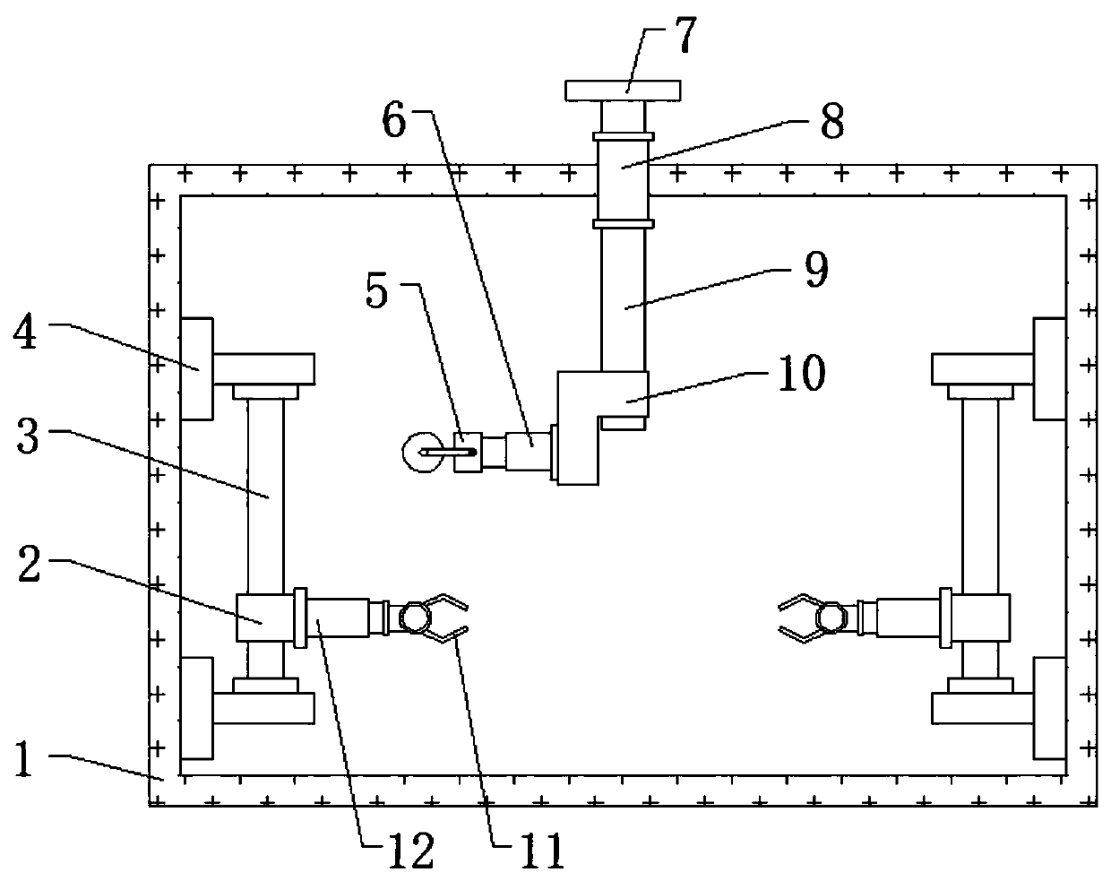
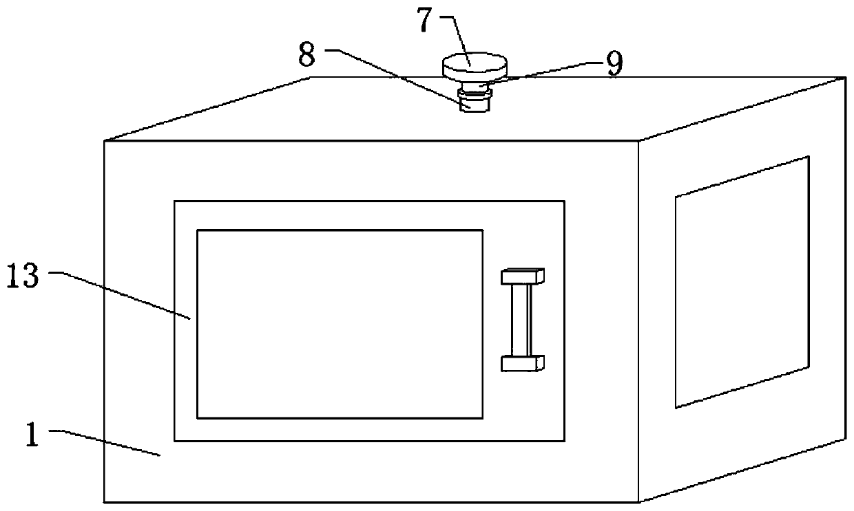
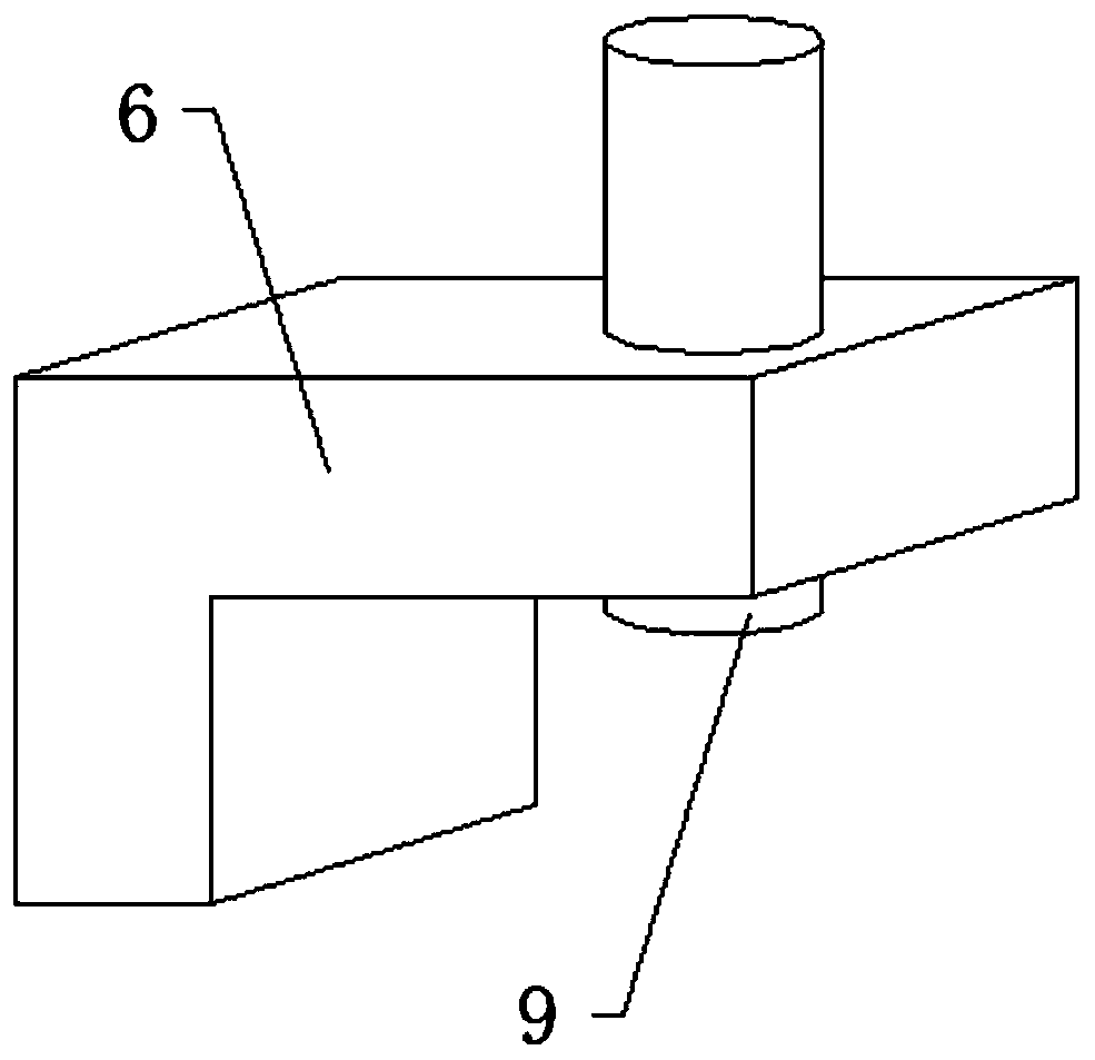
[0025] Reference Figure 1-3 , A polishing device for processing engine piston inserts, comprising a box body 1 and two clamping mechanisms. A mounting hole is opened in the middle of the outer wall of the top of the box body 1, and a sleeve 8 is inserted on the inner circumferential wall of the mounting hole. A connecting rod 9 is inserted into the circumferential inner wall of the sleeve 8, an L-shaped plate 10 is sleeved on the circumferential outer wall of the connecting rod 9, and a second electric telescopic rod 6 is fixed on one outer wall of the L-shaped plate 10 by bolts, One end of the extension rod of the second electric telescopic rod 6 is fixed with a polishing machine 5 by bolts, and a polishing sheet is hinged on one side of the outer wall of the polishing machine 5, and the clamping mechanisms are respectively located on both sides of the inside of the box body 1.

[0026] In the present invention, the top end of the connecting rod 9 is welded with a handle 7, and...

Embodiment 2

[0029] Reference Figure 4 , A polishing device for machining engine piston inserts. Compared with the first embodiment, this embodiment further includes a vacuum cleaner 14 which is fixed on one side of the inner wall of the top of the box 1 by bolts.

[0030] Working principle: When in use, during the polishing process, the vacuum cleaner 14 is started to vacuum, to avoid excessive dust inside the cabinet 1, and to ensure a clean working environment.


PUM


Abstract

The invention discloses a polishing device used for engine piston insert ring machining. The polishing device comprises a box body and two clamping mechanisms, a mounting hole is formed in the middleof the outer wall of the top of the box body, a casing pipe is inserted into the circumference inner wall of the mounting hole, a connecting rod is inserted into the circumference inner wall of the casing pipe, the circumference outer wall of the connecting rod is sleeved with an L plate, the outer wall of one side of the L plate is fixedly provided with a second electric telescopic rod through abolt, one end of an extension rod of the second electric telescopic rod is fixedly provided with a polishing machine through a bolt, and a polishing sheet is hinged to the outer wall of one side of the polishing machine. The connecting rod is rotated in the casing pipe, the polishing machine is driven to do circumference motion, the piston insert ring inner ring is polished, the polishing sheet ofthe polishing machine moves downwards, the piston insert ring outer ring is polished, and for difference sizes of piston insert rings, corresponding polishing is carried out through adjusting the length of the second electric telescopic rod.

Description

Technical field [0001] The invention relates to the technical field of polishing devices, and in particular to a polishing device for machining engine piston inserts. Background technique [0002] An engine is a machine that can convert other forms of energy into mechanical energy, including internal combustion engines, external combustion engines, electric motors, etc. For example, internal combustion engines usually convert chemical energy into mechanical energy. One of the components of the engine is the piston insert. The piston insert needs to be polished during the production process to ensure its smooth surface and the normal use of the piston insert and the engine. [0003] At present, most of the existing polishing devices for engine piston insert processing on the market have the following shortcomings during use: it is troublesome to polish the inner and outer rings of the piston insert. In summary, most existing engine piston inserts The polishing device for ring proce...

Claims


Application Information

Patent Timeline
IPC IPC(8): B24B29/04B24B41/06B24B55/06
CPCB24B29/04B24B41/06B24B55/06
Inventor 王涛姚玉军王聪
Owner SHIYAN TONGLU IND
Learn More