Multi-layer back flush anti-blocking artificial wetland system

A constructed wetland system, backwashing technology, applied in special treatment targets, water/sludge/sewage treatment, biological water/sewage treatment, etc. It can improve the efficiency of sewage treatment, increase the contact area, and save water resources.

Active Publication Date: 2019-10-11
CHINA INST OF WATER RESOURCES & HYDROPOWER RES
View PDF3 Cites 5 Cited by
  • Summary
  • Abstract
  • Description
  • Claims
  • Application Information

AI Technical Summary

Problems solved by technology

[0002] Constructed wetlands are an important means of solving lightly polluted sewage in the prior art. They are environmentally friendly and efficient, but constructed wetlands also have many disadvantages, such as easy blockage, etc.
The water flow state of the constructed wetland system is an important factor to maintain the normal operation of the system and ensure that the wetland can fully exert its purification effect. However, after clogging occurs, the permeability coefficient of the matrix will drop sharply, and the water passing capacity will also decrease. The treatment will lead to anaerobic fermentation due to lack of oxygen in the wetland, causing stench, breeding of mosquitoes and flies, and shortening the operating life of the constructed wetland;
[0003] The existing constructed wetlands are all laid horizontally. In terms of blockage removal, backwashing, chemical agents, or aeration of sewage are generally used. On the one hand, it costs a lot of water, but the effect is limited. On the other hand, chemical agents are used to remove blockages. It will also affect the entire ecosystem of the constructed wetland and affect the biological strains in the wetland;

Method used


Image

  • Multi-layer back flush anti-blocking artificial wetland system
  • Multi-layer back flush anti-blocking artificial wetland system
  • Multi-layer back flush anti-blocking artificial wetland system

Examples


Embodiment Construction

[0029] The present invention will be further described in detail below in conjunction with the embodiments, so that those skilled in the art can implement it with reference to the description.

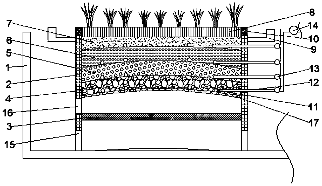
[0030] Such as Figure 1-3 As shown, the present invention provides a multi-level backwash anti-blocking artificial wetland system, including:

[0031] The outer pool 1 is provided with a sewage inlet at one corner, and the sewage inlet is provided with a block, and its aperture is 60-100 mesh, so as to intercept large pollutants and initially separate the sewage;

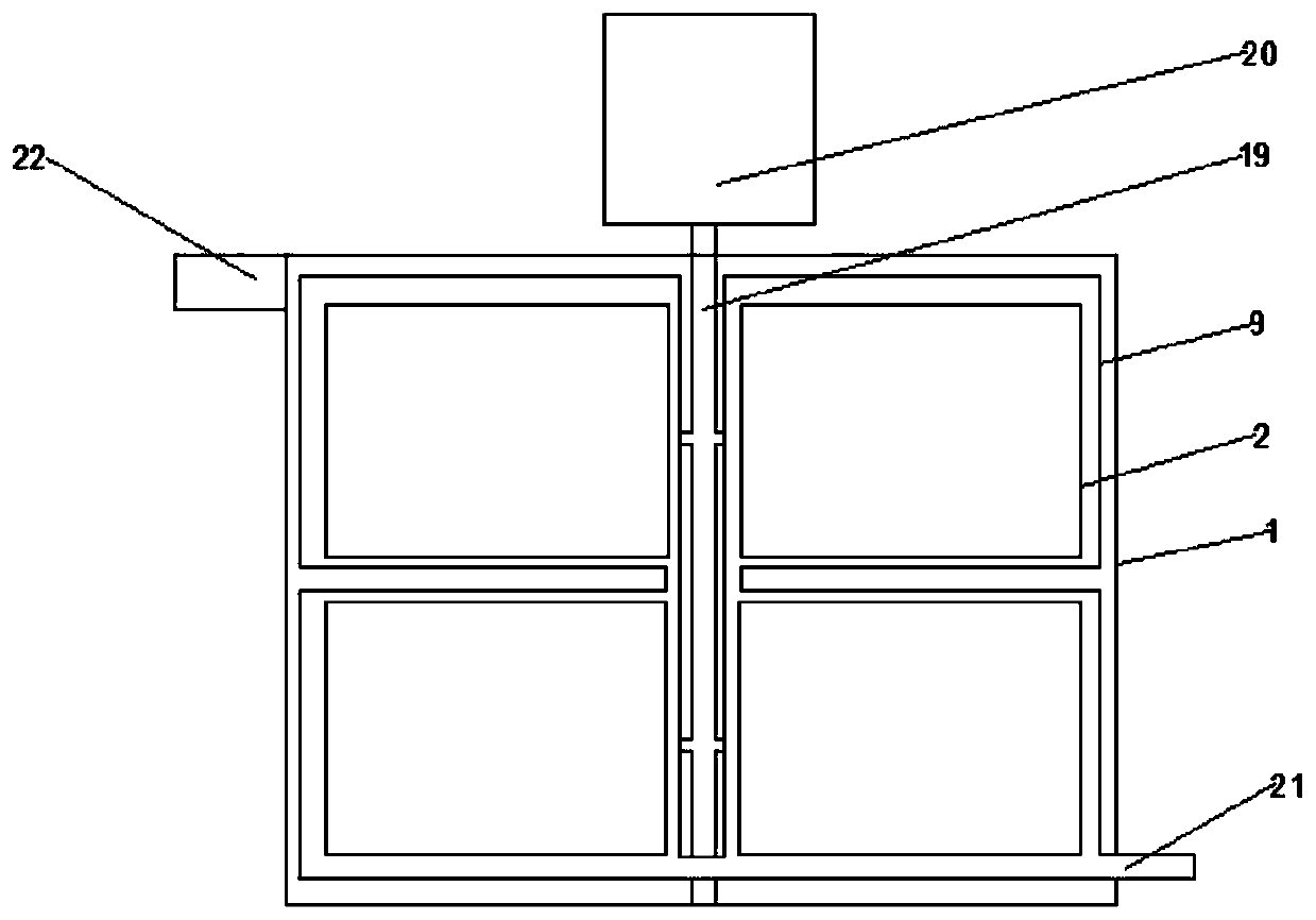
[0032] A plurality of sub-wetland systems are evenly spaced in the outer pool 1 and are at the same height as the outer pool 1. Specifically, they are evenly spaced in rows and rows, which saves land on the one hand and facilitates the distribution of pipelines on the other hand;

[0033] Each sub-wetland system includes:

[0034] Water partition wall 2, which is composed of four sides, enclosing a square space, the upper...


PUM

PropertyMeasurementUnit
thicknessaaaaaaaaaa
thicknessaaaaaaaaaa
thicknessaaaaaaaaaa

Abstract

The invention discloses a multi-layer back flush anti-blocking artificial wetland. The multi-layer back flush anti-blocking artificial wetland comprises an outer pond, an intercepting net, a pluralityof sub wetland systems, cutoff walls, secondary intercepting nets, a plurality of mud discharging ports, a plurality of filtration layers, bearing layers, pelelith layers, fine sand layers, light filler layers, organic layers, planting plates, aquatic plants, water collection grooves, a plurality of layers of back flush pipes, branch pipes, a total pipe, two sets of water outlets, conduits, clearwater outlets, an external air pump and a pressure water pump; the multi-layer back flush anti-blocking artificial wetland is simple in structure, the operation is convenient, flushing can be conducted on different layers according to the blockage conditions of the wetland, and the water outlets of the multi-layer back flush anti-blocking artificial wetland are formed to be of inclined structures, so that sprayed water forms a vortex shape; compared with a direct flow flushing mode, by adopting the mode, pollutants causing blockage on the filtration layers can be effectively removed, and thequick and efficient water saving back flush effect is achieved.

Description

technical field [0001] The invention relates to the technical field of artificial wetland sewage treatment. More specifically, the present invention relates to a multi-level backwashing anti-clogging artificial wetland system. Background technique [0002] Constructed wetlands are an important means of solving lightly polluted sewage in the prior art. They are environmentally friendly and efficient, but constructed wetlands also have many disadvantages, such as easy blockage. The water flow state of the constructed wetland system is an important factor to maintain the normal operation of the system and ensure that the wetland can fully exert its purification effect. However, after clogging occurs, the permeability coefficient of the matrix will drop sharply, and the water passing capacity will also decrease. The treatment will lead to anaerobic fermentation due to lack of oxygen in the wetland, causing stench, breeding of mosquitoes and flies, and shortening the operating l...

Claims


Application Information

Patent Timeline
Patent Type & Authority Applications(China)
IPC IPC(8): C02F3/32
CPCC02F3/32C02F2203/006C02F2303/14
Inventor 解莹杨春生彭文启渠晓东余杨张海萍张敏
Owner CHINA INST OF WATER RESOURCES & HYDROPOWER RES
Why Eureka
Try Eureka