Control Method of Permanent Magnet Synchronous Motor Based on Hall Position Sensor

A permanent magnet synchronous motor, Hall position technology, applied in motor generator control, electronic commutation motor control, control system and other directions, can solve the problem of excessive estimation result deviation, torque and current fluctuation, torque fluctuation, etc. The effect of increasing starting torque, reducing torque fluctuation, and reducing torque fluctuation

Active Publication Date: 2021-03-30
HEBEI UNIV OF TECH
View PDF4 Cites 0 Cited by
  • Summary
  • Abstract
  • Description
  • Claims
  • Application Information

AI Technical Summary

Problems solved by technology

In the existing engineering technology, the permanent magnet synchronous motor using the Hall position sensor adopts a 180-degree square wave current drive mode when starting, and then cuts into the sinusoidal current drive when the motor speed rises to a certain level [1] , but this method has insufficient torque during the low-speed start-up process of the motor, and there will be a large torque fluctuation when cutting into the sinusoidal current drive (the torque will suddenly increase when the square wave current changes to the sine wave current, resulting in fluctuations)
While the sinusoidal current drives the permanent magnet synchronous motor, it is necessary to estimate the position of the rotor in real time and use six discrete positions to correct the estimated results, but the correction in the prior art is blunt and directly replaces the estimated results with accurate discrete positions (If it is found that the estimated position deviates from the real position, replace the estimated result with the real position, such as the estimated electrical angle is 150 degrees, the real electrical angle is 180 degrees, and the electrical angle will directly change from 150 to 180, resulting in torque fluctuations
) [2] , sometimes the deviation of the estimation result is too large, which will cause the fluctuation of torque and current

Method used


Image

  • Control Method of Permanent Magnet Synchronous Motor Based on Hall Position Sensor
  • Control Method of Permanent Magnet Synchronous Motor Based on Hall Position Sensor
  • Control Method of Permanent Magnet Synchronous Motor Based on Hall Position Sensor

Examples


Embodiment

[0057] In this embodiment, the control method of the permanent magnet synchronous motor based on the Hall position sensor adopts the Nanpu 1.2KW permanent magnet synchronous motor as the controlled object, and the specific implementation steps are as follows:

[0058] 1) Open the three-phase electric circuit of the motor, drag it up at the rated speed, then connect the negative pole of the oscilloscope probe to the W phase, and the positive pole to the V pole to obtain the back electromotive force waveform.

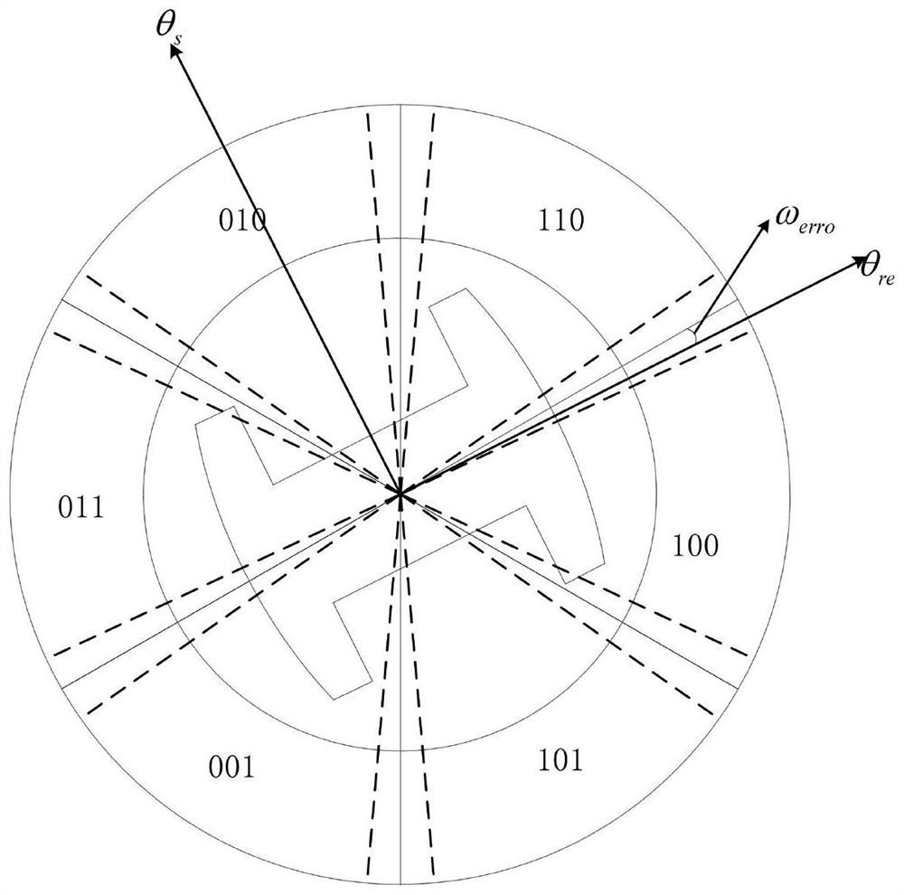
[0059] 2) Connect the outputs A, B, and C of the Hall position sensor of the motor to the positive pole of the oscilloscope test lead, and the negative pole of the test lead to the negative pole of the Hall position sensor power supply, and compare it with the back electromotive force waveform obtained in step 1.1 to obtain the position sensor. Along the corresponding six discrete electrical angles θ r1 =27.6°, θ r2 =92.4°, θ r3 =147.2°, θ r4 =207.5°, θ r5 =272.3°, θ ...


PUM


Abstract

The invention relates to a control method of a permanent magnet synchronous motor based on a Hall position sensor. The method includes the following steps: S1, correcting the electric angle of a motorrotor corresponding to a Hall signal, and obtaining six discrete electric angles theta r1, theta r2, theta r3, theta r4, theta r5 and theta r6 corresponding to the rising edge and falling edge of theHall position sensor; S2, calculating the rotor speed of the rotor flux, wherein the rotor speed omega r is the average speed between the edges of two adjacent hall jumps, that is, the rotor speed isthe quotient of the electric angle between the edges of two adjacent hall jumps and the time interval; S3, using a field oriented control technology and a gradual 180-degree current soft switching sinusoidal current mode to drive the permanent magnet synchronous motor; and S4, adjusting the rotation speed omega s and position of the stator flux through a phase locking mechanism in the operation process to control the permanent magnet synchronous motor. The method reduces the torque ripple caused by the switching from 180-degree square wave current drive to sinusoidal current drive, and avoidsthe sudden change of the stator flux direction and reduces the torque ripple.

Description

technical field [0001] The invention relates to the technical field of motor control, in particular to a control method of a permanent magnet synchronous motor based on a Hall position sensor. Background technique [0002] In a high-performance permanent magnet synchronous motor control system, in order to adjust the rotor speed and position, it is generally necessary to install a position sensor at the motor rotor shaft end for closed-loop control of the speed and position. Commonly used high-precision position sensors include photoelectric encoders and resolvers, but these sensors will bring many problems in practical applications, such as complex hardware structure, increased system cost, increased interface and cables leading to reduced system reliability, and the introduction of electromagnetic interference, etc. . The switch-type Hall position sensor has the characteristics of simple installation, small size and low cost, but it can only provide six accurate position ...

Claims


Application Information

Patent Timeline
Patent Type & Authority Patents(China)
IPC IPC(8): H02P21/05H02P21/08H02P21/12
CPCH02P21/05H02P21/08H02P21/12
Inventor 李练兵李铎陈黎郭嘉仪谢朋朋王佳赵思锋唐英伟贾志旺常文祥
Owner HEBEI UNIV OF TECH
Why Eureka
Try Eureka