Luminous color-changing monofilament and preparation method thereof
A monofilament, color-changing fiber technology, applied in rayon manufacturing, hollow filament manufacturing, single-component polyester rayon, etc., can solve the problems of no active rigidity, environmental pollution, variable color effects, etc. glossy effect
- Summary
- Abstract
- Description
- Claims
- Application Information
AI Technical Summary
Problems solved by technology
Method used
Image
Examples
Embodiment 1
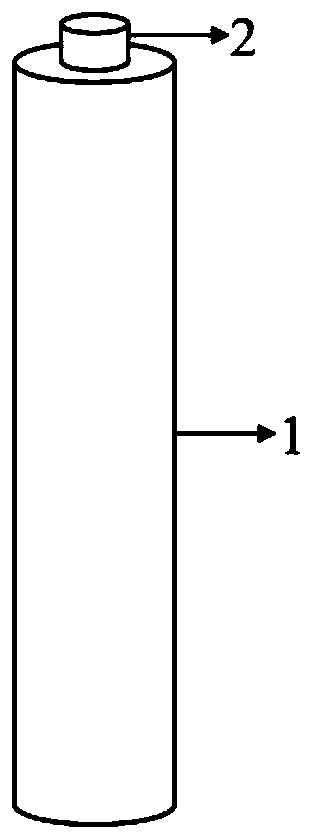
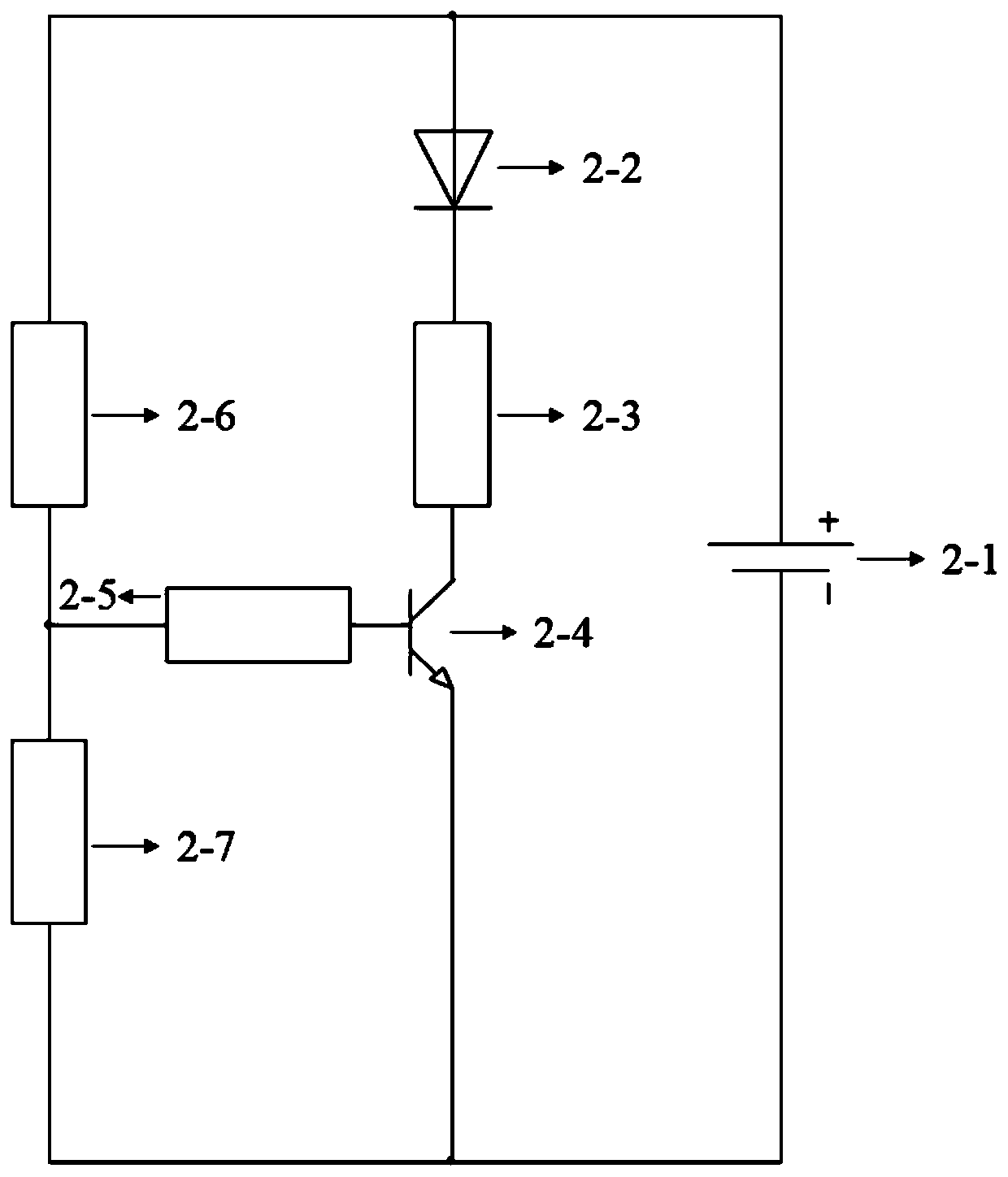
[0031] A luminous color-changing monofilament of this embodiment has a schematic structural diagram such as figure 1 As shown, it is composed of a color-changing fiber monofilament 1 and an LED light strip 2, one end of the color-changing fiber monofilament 1 is thermally bonded to the LED light strip 2. The circuit diagram of the LED strip is as follows figure 2 As shown, including power supply 2-1, LED light 2-2, resistor R1 (100K) 2-3, triode (s9013) 2-4, resistor R2 (4.7K) 2-5, resistor R3 (220K) 2-6 And the photoresistor (GL3516) 2-7; one end of the LED lamp is connected to the positive electrode of the power supply, the other end of the LED lamp is connected to the resistor R1 (100K), one end of the resistor R1 (100K) is connected to the LED lamp, and the resistor R1 (100K) The other end of) is connected to the collector of the triode (s9013), the collector of the triode (s9013) is connected to the resistor R1 (100K), the emitter of the triode (s9013) is connected to the...
Embodiment 2
[0036] A luminous color-changing monofilament of this embodiment has a schematic structural diagram such as figure 1 As shown, it is composed of a color-changing fiber monofilament 1 and an LED light strip 2, one end of the color-changing fiber monofilament 1 is thermally bonded to the LED light strip 2. The circuit diagram of the LED strip is as follows figure 2 As shown, including power supply 2-1, LED light 2-2, resistor R1 (100K) 2-3, triode (s9013) 2-4, resistor R2 (4.7K) 2-5, resistor R3 (220K) 2-6 And the photoresistor (GL3516) 2-7; one end of the LED lamp is connected to the positive electrode of the power supply, the other end of the LED lamp is connected to the resistor R1 (100K), one end of the resistor R1 (100K) is connected to the LED lamp, and the resistor R1 (100K) The other end of) is connected to the collector of the triode (s9013), the collector of the triode (s9013) is connected to the resistor R1 (100K), the emitter of the triode (s9013) is connected to the...
Embodiment 3
[0041] A luminous color-changing monofilament of this embodiment has a schematic structural diagram such as figure 1 As shown, it is composed of a color-changing fiber monofilament 1 and an LED light strip 2, one end of the color-changing fiber monofilament 1 is thermally bonded to the LED light strip 2. The circuit diagram of the LED strip is as follows figure 2 As shown, including power supply 2-1, LED light 2-2, resistor R1 (100K) 2-3, triode (s9013) 2-4, resistor R2 (4.7K) 2-5, resistor R3 (220K) 2-6 And the photoresistor (GL3516) 2-7; one end of the LED lamp is connected to the positive electrode of the power supply, the other end of the LED lamp is connected to the resistor R1 (100K), one end of the resistor R1 (100K) is connected to the LED lamp, and the resistor R1 (100K) The other end of) is connected to the collector of the triode (s9013), the collector of the triode (s9013) is connected to the resistor R1 (100K), the emitter of the triode (s9013) is connected to the...
PUM
| Property | Measurement | Unit |
|---|---|---|
| Fiber diameter | aaaaa | aaaaa |
Abstract
Description
Claims
Application Information
 - R&D
- Intellectual Property
- Life Sciences
- Materials
- Tech Scout
- Unparalleled Data Quality
- Higher Quality Content
- 60% Fewer Hallucinations
Browse by: Latest US Patents, China's latest patents, Technical Efficacy Thesaurus, Application Domain, Technology Topic, Popular Technical Reports.
© 2025 PatSnap. All rights reserved.Legal|Privacy policy|Modern Slavery Act Transparency Statement|Sitemap|About US| Contact US: help@patsnap.com


