Constant pressure polishing device and constant pressure polishing method for aspheric optical element

A technology of optical components and polishing devices, which is applied to surface polishing machine tools, grinding drive devices, optical surface grinders, etc., and can solve problems such as polishing head fluctuations and unfavorable workpiece processing

Active Publication Date: 2021-07-06
广州精点科技有限公司
View PDF8 Cites 0 Cited by
  • Summary
  • Abstract
  • Description
  • Claims
  • Application Information

AI Technical Summary

Problems solved by technology

However, this compensation method is more suitable for workpieces with consistent surface dimensions, which can ensure the stability of feed rate and contact pressure; for curved surface processing components, when different processing positions on the curved surface are in contact with the polishing head, each processing position is different from the polishing head. The contact pressure between the polishing heads changes in real time, causing real-time fluctuations in the polishing heads, and at the same time the feed rate changes in real time, that is, the processing parameters such as contact pressure and feed rate change in real time, which is very unfavorable to the workpiece processing. should be avoided as much as possible in

Method used


Image

  • Constant pressure polishing device and constant pressure polishing method for aspheric optical element
  • Constant pressure polishing device and constant pressure polishing method for aspheric optical element
  • Constant pressure polishing device and constant pressure polishing method for aspheric optical element

Examples


Embodiment Construction

[0039] The following will clearly and completely describe the technical solutions in the embodiments of the present invention with reference to the accompanying drawings in the embodiments of the present invention. Obviously, the described embodiments are only some, not all, embodiments of the present invention. Based on the embodiments of the present invention, all other embodiments obtained by persons of ordinary skill in the art without making creative efforts belong to the protection scope of the present invention.

[0040] The core of the present invention is to provide a constant-pressure polishing device and a constant-pressure polishing method for an aspheric optical element, which have high polishing precision and good polishing uniformity.

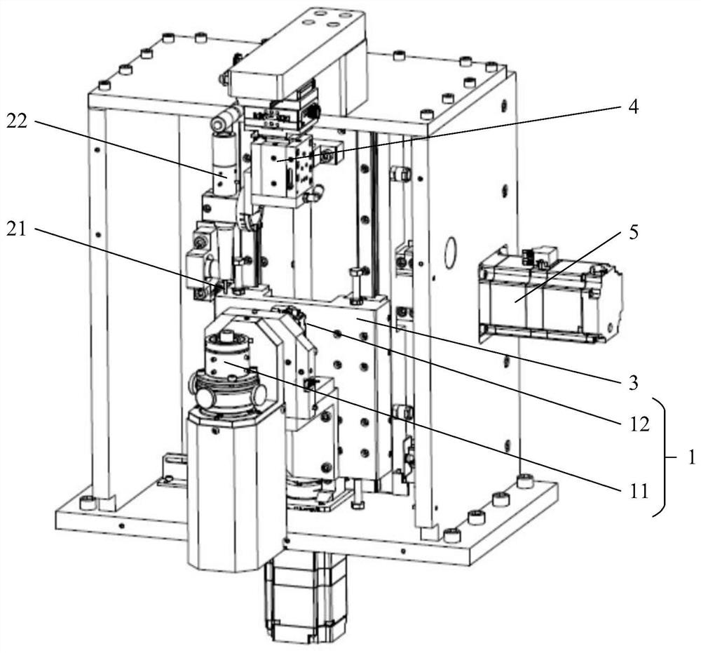
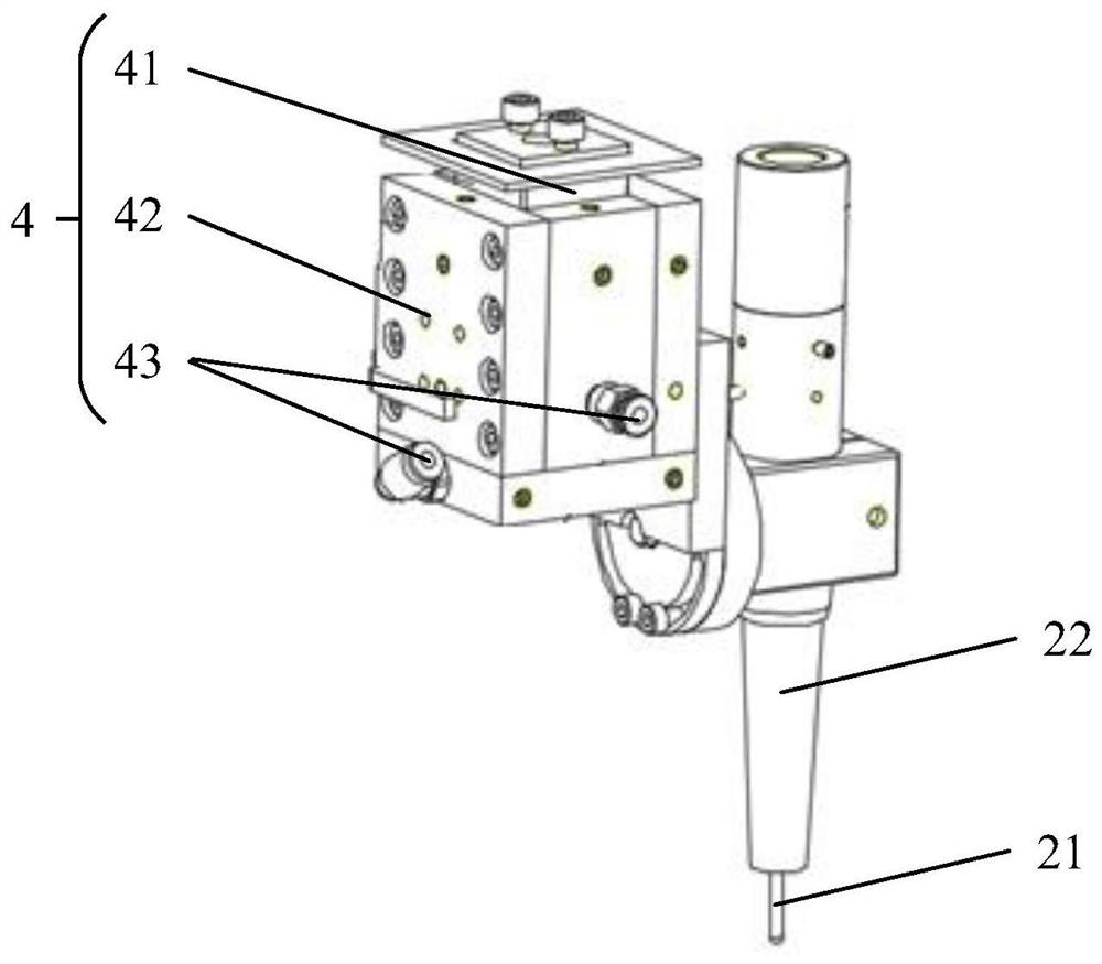
[0041] Please refer to Figure 1 to Figure 3 , figure 1 A schematic structural view of a constant-pressure polishing device for an aspheric optical element provided in a specific embodiment of the present invention; figure 2 f...


PUM


Abstract

The invention discloses a constant-pressure polishing device for an aspheric optical element, which comprises: a rotating assembly for setting a workpiece and driving the workpiece to rotate; a polishing piece for contacting with the workpiece and polishing the workpiece; The polishing shaft; the first linear driving device connected with the rotating assembly, used to drive the rotating assembly to move linearly, so that the workpiece moves along the axial direction of the polishing shaft; the motion controller connected with the rotating assembly and the first linear driving device, It is used to control the synchronous movement of the rotary assembly and the first linear drive device. The output displacement of the first linear drive device has a preset corresponding relationship with the output rotation angle of the rotary assembly, so that the output displacement compensates the machining of the workpiece surface during the rotation of the rotary assembly. The positional difference in the axial direction of the polishing axis. The constant pressure polishing device has high processing precision, can ensure the stability of the polishing removal amount, and makes the polishing uniform and reliable. The invention also discloses a constant pressure polishing method for the aspheric optical element.

Description

technical field [0001] The invention relates to the technical field of optical element processing equipment, and more specifically relates to a constant-pressure polishing device for aspheric optical elements. In addition, the present invention also relates to a constant-pressure polishing method for an aspheric optical element, which is applied to a constant-pressure polishing device for the above-mentioned aspheric optical element. Background technique [0002] In the field of precision and ultra-precision machining technology, the polishing accuracy of optical components has an important impact on the optical performance of the optical system. In the process of polishing optical components, the contact pressure between the polishing head and the processing element is the key factor affecting the removal amount of the workpiece surface. The contact pressure between the polishing head and the processing element is unstable, which will lead to the polishing of the workpiece ...

Claims


Application Information

Patent Timeline
Patent Type & Authority Patents(China)
IPC IPC(8): B24B13/00B24B29/02B24B47/12B24B47/20
CPCB24B13/00B24B29/02B24B47/12B24B47/20
Inventor 卓少木姚洪辉朱相优黄松明张嘉荣蔡晓誉
Owner 广州精点科技有限公司
Why Eureka
Try Eureka