
Exhaust gas purifying device

A technology for exhaust gas purification and equipment, applied in chemical instruments and methods, combined devices, dispersed particle separation, etc., can solve the problems of high investment cost, complex operation management, low utilization rate of light energy, etc., and achieve easy maintenance, replacement, and operation management. Simple, low investment cost effect

Pending Publication Date: 2019-09-20
苏州罗克韦尔智能科技有限公司
View PDF0 Cites 4 Cited by
  • Summary
  • Abstract
  • Description
  • Claims
  • Application Information

AI Technical Summary

Problems solved by technology

[0002] With the development of industry, industrial manufacturing often produces industrial waste gas. In order to protect the environment, the gas needs to be treated before it can be discharged into the air. For low-concentration waste gas, a single low-temperature plasma equipment or UV photocatalytic oxidation equipment can treat the waste gas. However, the treatment effect on high-concentration waste gas is limited, and low-temperature plasma equipment has high requirements on the configuration design, manufacturing accuracy, and rigor of equipment components, such as parameters such as electric field frequency, voltage, and high-frequency pulses. If one of the parameters fails to meet the requirements, such as low voltage, too high or too low frequency, etc., it will have a great impact on the generation of ions; in addition, the absorption range of ultraviolet light in UV photocatalytic oxidation equipment is narrow , the utilization rate of light energy is low, and its efficiency is also limited by the nature of the catalyst, the wavelength of ultraviolet light and the reactor, and under certain conditions, the photocatalyst is easily deactivated
[0003] When the exhaust gas humidity is too high and contains a certain amount of particulate matter, it will reduce the service life and purification efficiency of low-temperature plasma equipment and UV photocatalytic oxidation equipment. In severe cases, even hazardous accidents may occur. For high humidity, high concentration, complex components and For organic waste gas containing a certain amount of particulate matter, it is conventional to adopt individual process equipment to be combined in series through pipelines to achieve good treatment effects. However, this treatment method has high investment costs, large floor space, and more complicated operation management. Based on the above defects and deficiencies, it is necessary to improve the existing technology and design a waste gas purification equipment

Method used


Image

  • Exhaust gas purifying device
  • Exhaust gas purifying device
  • Exhaust gas purifying device

Examples


Embodiment Construction

[0025] The preferred embodiments of the present invention will be described in detail below in conjunction with the accompanying drawings, so that the advantages and features of the invention can be more easily understood by those skilled in the art, so as to define the protection scope of the present invention more clearly.

[0026] see Figure 1 to Figure 8 , the embodiment of the present invention includes:

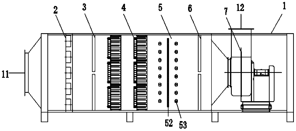
[0027] A kind of waste gas purification equipment, this kind of waste gas purification equipment comprises a housing 1, the air inlet 11 is provided at one end of the housing 1, and the air outlet 12 is provided at the upper part of the other end of the housing 1, from the air inlet 11 to the air outlet The casing 1 of 12 is sequentially inserted with a centrifugal defogging area 2, an initial effect filter area 3, a low-temperature plasma area 4, a UV photolysis area 5, a final effect filter area 6, and a centrifugal fan 7. The inner wall of the shell 1 is provided wi...


PUM


Abstract

The invention discloses an exhaust gas purifying device. The exhaust gas purifying device comprises a casing. An air inlet is arranged at one end of the casing, and an air outlet is arranged on the upper portion of the other end of the casing. A centrifugal defogging zone, a primary effect filtration zone, a low temperature plasma zone, a UV photolysis zone, a final effect filtration zone and a centrifugal fan are sequentially inserted into the casing from the air inlet to the air outlet. Corresponding insertion grooves are formed in the inner wall of the casing. The centrifugal defogging zone comprises a support and centrifugal defogging devices. The centrifugal defogging devices are in array arrangement on the support matched with the insertion grooves. The primary effect filtration zone comprises a filtering frame and filtering cotton. The filtering cotton is sealed on the filtering frame matched with the insertion grooves. The exhaust gas purifying device has the advantages that the exhaust gas purifying device is compact in structure and reasonable in design, can treat high-humidity and high-concentration exhaust gases comprising complicated components and certain particles, and has low investment cost; the insertion structure facilitates maintenance and replacement, and operation and management are simple.

Description

technical field [0001] The invention relates to the technical field of environmental protection purification, in particular to a waste gas purification equipment. Background technique [0002] With the development of industry, industrial manufacturing often produces industrial waste gas. In order to protect the environment, the gas needs to be treated before it can be discharged into the air. For low-concentration waste gas, a single low-temperature plasma equipment or UV photocatalytic oxidation equipment can treat the waste gas. However, the treatment effect on high-concentration waste gas is limited, and low-temperature plasma equipment has high requirements on the configuration design, manufacturing accuracy, and rigor of equipment components, such as parameters such as electric field frequency, voltage, and high-frequency pulses. If one of the parameters fails to meet the requirements, such as low voltage, too high or too low frequency, etc., it will have a great impact...

Claims


Application Information

Patent Timeline
Patent Type & Authority Applications(China)
IPC IPC(8): B01D50/00B01D53/86B01D53/74
CPCB01D53/74B01D53/32B01D53/86B01D2255/802B01D2255/20707B01D50/20
Inventor 胡秀林
Owner 苏州罗克韦尔智能科技有限公司
Learn More