Gantry type manipulator removable spinal surgery robot

A surgical robot and robotic arm technology, applied in the field of surgical robots, can solve problems such as difficulty in improving precision, difficulty in expansion and upgrading, and difficulty in switching instruments, so as to avoid occupying operating room space, improve flexibility and precision, and improve operation convenience. Effect

Pending Publication Date: 2019-09-20
SUZHOU DIANHE MEDICAL TECH
View PDF0 Cites 1 Cited by
  • Summary
  • Abstract
  • Description
  • Claims
  • Application Information

AI Technical Summary

Problems solved by technology

[0003] 1. The light load and rigidity are poor. For example, the spinal surgery robot fixed on the spinous process of the human body cannot be heavily loaded. The articulated robotic arm robot mounted on the trolley is also a light-load robot. The robotic arm is a very long cantilever structure. The end only carries a guide tube to guide the placement of the pedicle screw. If the end of the mechanical arm needs to carry a heavy instrument, it is prone to deformation
[0004] 2. The overall system of the robot is complex. In addition to the robot, the system needs the cooperation of navigation, ISO-3D or O-arm machine to complete the operation.
[0005] 3. It is difficult to further improve the accuracy. Due to the above-mentioned system structure reasons, there are many error links, so that the improvement of the overall operation accuracy of the robot encounters a bottleneck problem, and it is difficult to further improve the accuracy.
[0006] 4. It is difficult to switch instruments, the function is single, and it is difficult to expand and upgrade. Most of them have a single robotic arm structure, which affects the realization of multifunctional spinal surgery.
[0007] 5. The volume is large, and patients are prone to psychological fear

Method used


Image

  • Gantry type manipulator removable spinal surgery robot
  • Gantry type manipulator removable spinal surgery robot
  • Gantry type manipulator removable spinal surgery robot

Examples


Embodiment Construction

[0056] The specific implementation manners of the present invention will be further described in detail below in conjunction with the accompanying drawings and embodiments. The following examples are used to illustrate the present invention, but are not intended to limit the scope of the present invention.

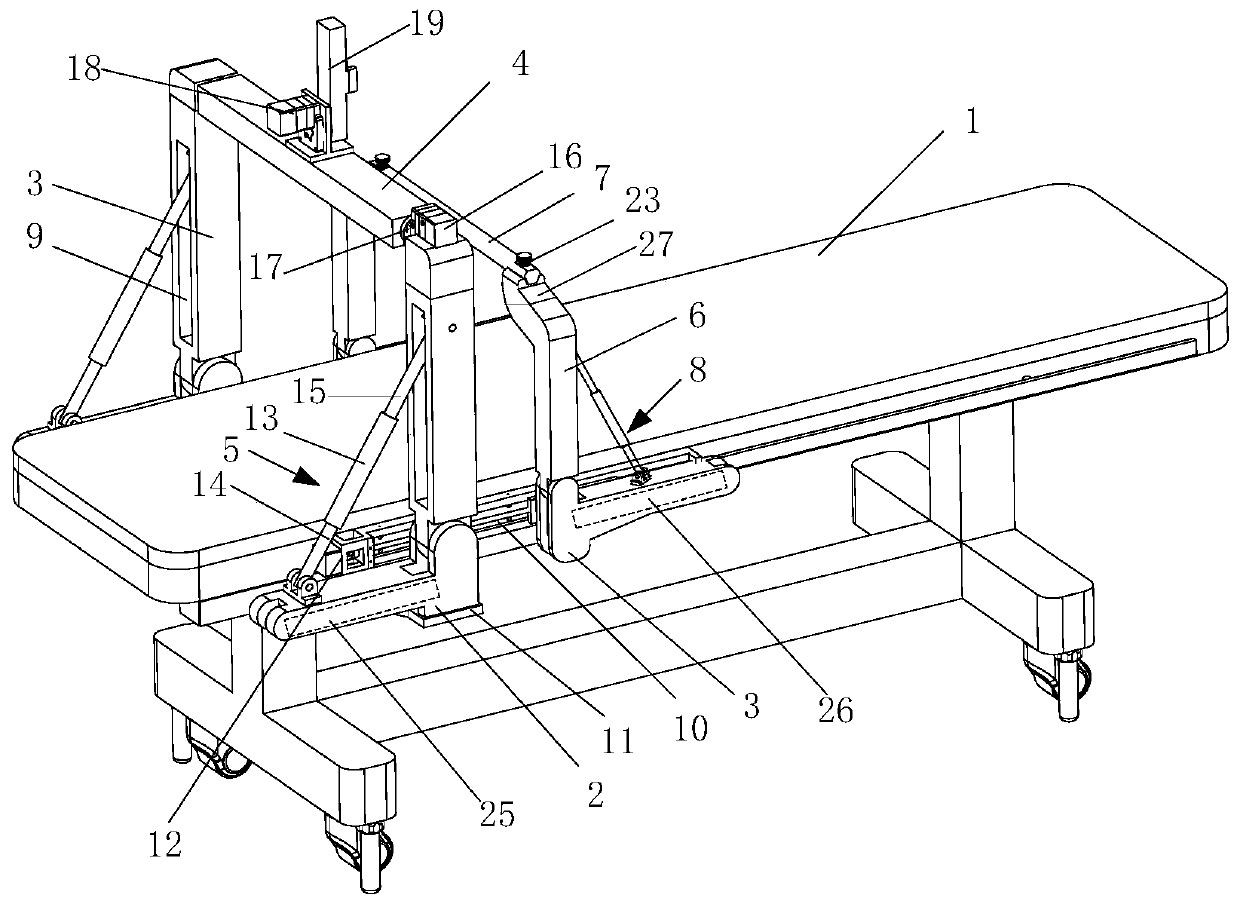
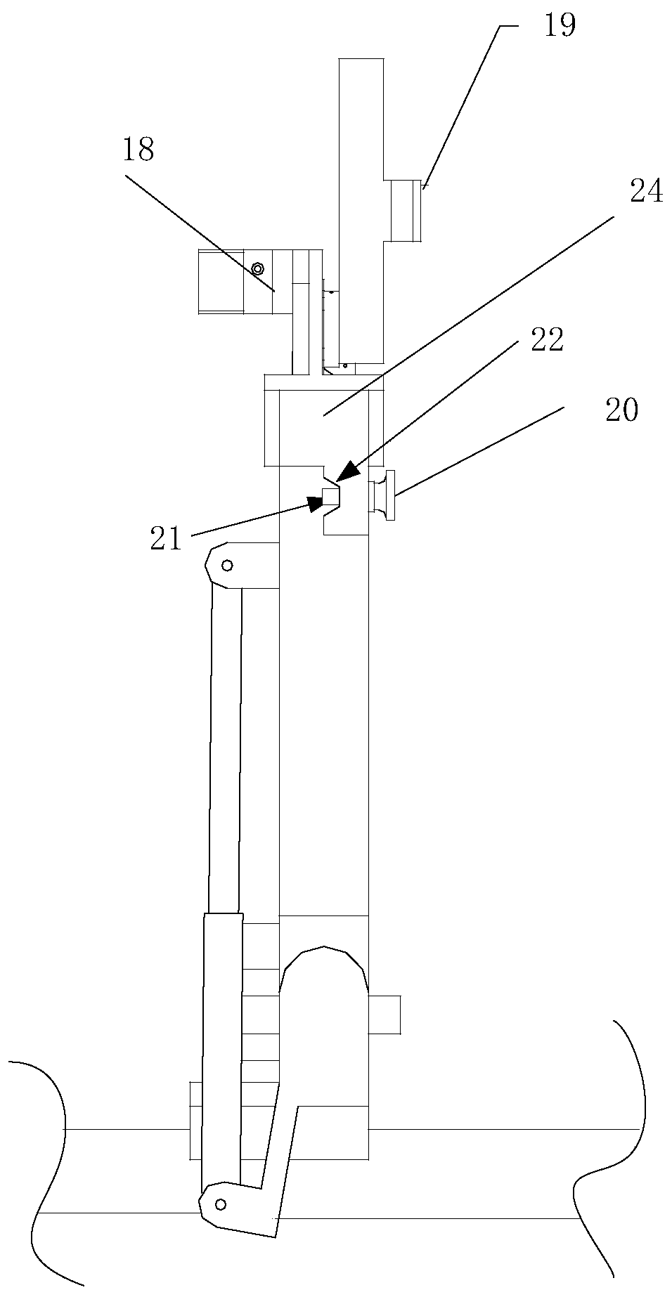
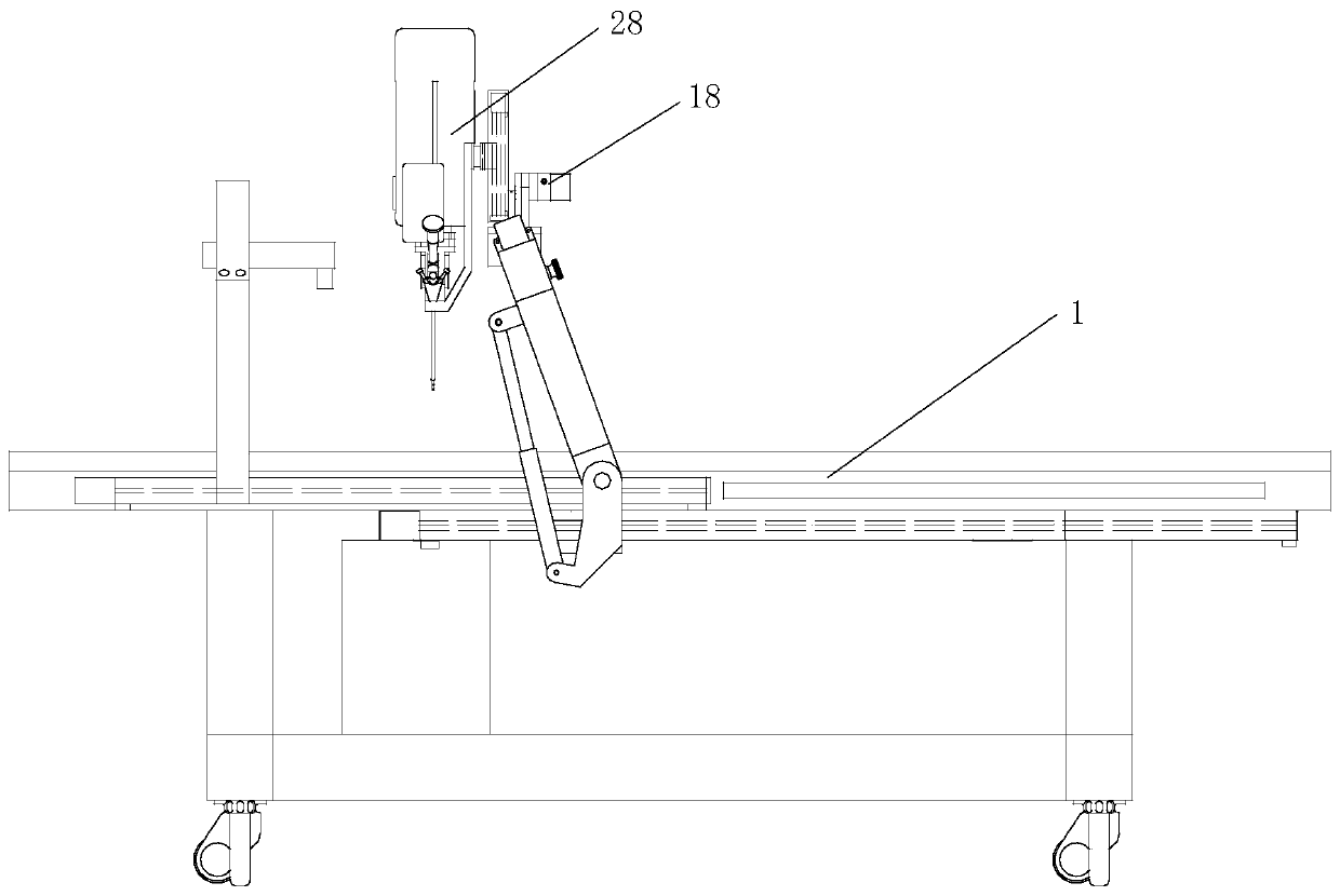
[0057] Such as Figures 1 to 5A gantry-type retractable robot for spine surgery includes an operating table 1, and X-direction control devices are provided in pairs on both sides of the operating table 1 in order to realize the X-direction movement adjustment of the subsequently installed surgical instruments. Simultaneously, the main swing arm 3 is installed on the X-direction guiding control device through the main connecting seat 2, and the main push rod 25 is also installed on the main connecting seat 2. The main push rod 25 is connected with the lower end of the main swing arm 3 and promotes the swing of the main swing arm 3 . Moreover, the upper end of the main con...


PUM


Abstract

The invention relates to a gantry type manipulator removable spinal surgery robot. The gantry type manipulator removable spinal surgery robot comprises an operation table, X-direction guide control devices are arranged on two sides of the operation table in pairs, main swing arms are installed on the X-direction guide control devices through a main connecting base, main push bars are further installed on the main connecting base, each main push bar is connected to the lower end of each main arm to push the main arm to swing, the upper end connected with the main swing arms, of the main connecting base is connected with main positioning locks, a Y-direction guide device is further connected onto the main swing arms, a Z-direction guide control device is connected onto the Y-direction guide device, and main gantry manipulators are formed. The robot can map the surface coordinates of vertebrae in vitro, which is convenient to collect coordinate data of the bone surface accurately and rapidly, random switching of orthopaedic powder, pliers, soft tissue resection tools and other instruments can be realized through a drum instrument bank under the condition of 'heavy load', and precision operation of various different spinal surgery can be completed in the whole process; the advantages of large bearing capacity, good rigidity, dexterous structure, strong expansibility and the like are achieved.

Description

technical field [0001] The invention relates to a surgical robot, in particular to a gantry-type retractable mechanical arm spinal surgery robot. Background technique [0002] In recent years, some spinal surgery robots have been successfully applied clinically, such as the Mazor spine assistant in Israel, the SPINEBOT spine robot in South Korea, and the Mazor X spine surgery robot in the United States. Some of them are fixed on the spinous processes of the human body. The structure of the articulated robotic arm mounted on the trolley is currently facing the following problems: [0003] 1. The light load and rigidity are poor. For example, the spinal surgery robot fixed on the spinous process of the human body obviously cannot be overloaded. The articulated robotic arm robot mounted on the trolley is also a light-load robot. The robotic arm is a very long cantilever structure. The end only carries a guide tube to guide the placement of the pedicle screw, and the end of the...

Claims


Application Information

Patent Timeline
IPC IPC(8): A61B34/30
CPCA61B34/30A61B2034/304
Inventor 张春霖
Owner SUZHOU DIANHE MEDICAL TECH
Why Eureka
Try Eureka