


Quick Research
Generate reliable direction feasibility study reports for your R&D in just a few steps.

Technical Q&A
Discover and master advanced knowledge NOW. Basics, ideas, possibilities, all at once.

Find Solutions
As an expert in R&D theories, this can generate solutions to your technical problems instantly.

Evaluate Feasibility
Analyze your overall solution with one click, know your potential R&D risks in advance.

Monitor Landscape
Get weekly tech updates, stay abreast of the latest tech innovations and key insights.
A kind of paper deacidification equipment
A deacidification and equipment technology, which is applied in paper, papermaking, waste paper post-processing, etc., can solve the problems of inconvenient liquid replenishment operation, inconvenient maintenance of air compressor, and small space, etc., and achieves simple structure, shortened drying time, and reduced work intensity Effect
- Summary
- Abstract
- Description
- Claims
- Application Information
AI Technical Summary
Problems solved by technology
Method used
Image

Examples
Embodiment 1
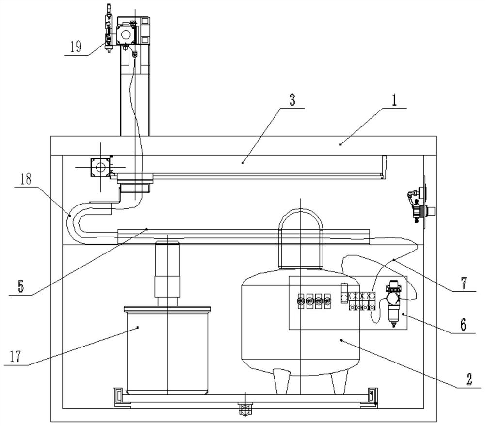
[0035] Such as figure 1 and 2 As shown, a paper deacidification equipment includes a workbench panel 1, an installation cavity is provided at the bottom of the workbench panel 1, and a stirring tank 17 and an air compressor 2 are arranged in the installation cavity, and a manipulator assembly and a blower diffuser are also included. device, the manipulator assembly includes an X-axis manipulator arranged on the lower part of the workbench panel 1 along the long side of the workbench panel 1, and an X-axis manipulator arranged on the upper part of the workbench panel 1 along the broad side of the workbench panel 1 The Y-axis manipulator running in the direction and the U-shaped support for connecting the X-axis manipulator and the Y-axis manipulator, the Y-axis manipulator is equipped with a liquid nozzle 19 for spraying deacidification liquid, and the liquid nozzle 19 is connected with the mixing tank 17; The air blowing diffuser includes an air control valve group 6, a gas p...
Embodiment 2
[0041] Such as figure 1 As shown, this implementation is further optimized on the basis of Embodiment 1. This embodiment focuses on the improvements compared with Embodiment 1, and the similarities will not be repeated. In this embodiment, the X-axis manipulator Including the first linear module 3, the first motor 4, the first drag chain 18 and the first chain slot 5, the first linear module 3 is installed on the bottom of the workbench panel 1, the first motor 4 and the first straight The line module 3 is connected, the first chain slot 5 is installed on the bracket below the first line module 3, the first drag chain 18 is arranged in the first chain slot 5, and the bottom of the U-shaped bracket is fixed on the first straight line On the module 3, one end of the first drag chain 18 is fixed in the first chain slot 5, and the other end of the first drag chain 18 is connected to the bottom of the U-shaped bracket. The first linear module 3 is a belt linear module, the first m...
Embodiment 3
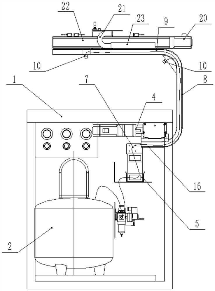
[0046] Such as figure 2 As shown, this implementation is further optimized on the basis of Embodiment 2. This embodiment focuses on the improvements compared with Embodiment 1, and the similarities will not be repeated. In this embodiment, the trachea 7 is sequentially It is arranged in the first drag chain 18 , the first section of the pole 16 , the second section of the pole 8 and the third section of the pole 9 , and the gas spray head 10 is installed on the third section of the pole 9 .
[0047] Preferably, a first chamfer is provided at the connection between the first section rod 16 and the second section rod 8, and a second chamfer is provided at the connection place between the second section rod 8 and the third section rod 9 , the gas shower head 10 is installed at the second chamfer, and there is a certain angle between the gas shower head 10 at the second chamfer and the workbench panel 1 . The setting of the first chamfer and the second chamfer can prevent the co...
PUM
 Abstract
Description
Claims
Application Information
 - R&D Engineer
- R&D Manager
- IP Professional
- Industry Leading Data Capabilities
- Powerful AI technology
- Patent DNA Extraction
Browse by: Latest US Patents, China's latest patents, Technical Efficacy Thesaurus, Application Domain, Technology Topic, Popular Technical Reports.
© 2024 PatSnap. All rights reserved.Legal|Privacy policy|Modern Slavery Act Transparency Statement|Sitemap|About US| Contact US: help@patsnap.com