Paper deacidification device
A deacidification and equipment technology, applied in paper, papermaking, waste paper post-processing, etc., can solve the problems of inconvenient maintenance of air compressors, inconvenient liquid replenishment operations, and small space, and achieve shortened drying time, simple structure, and reduced work intensity. Effect
- Summary
- Abstract
- Description
- Claims
- Application Information
AI Technical Summary
Problems solved by technology
Method used
Image

Examples
Embodiment 1
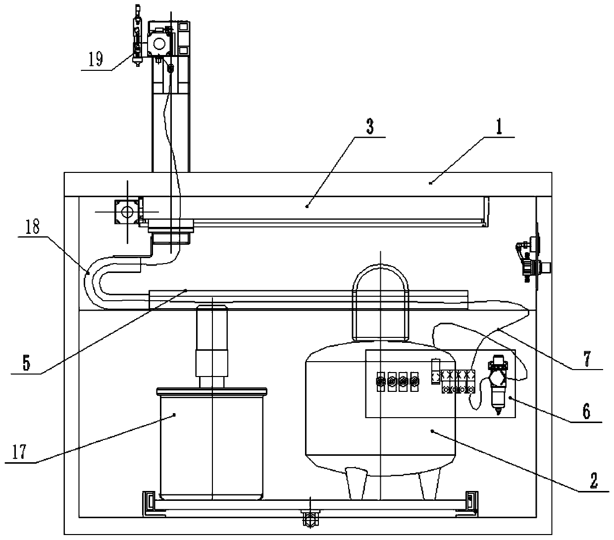
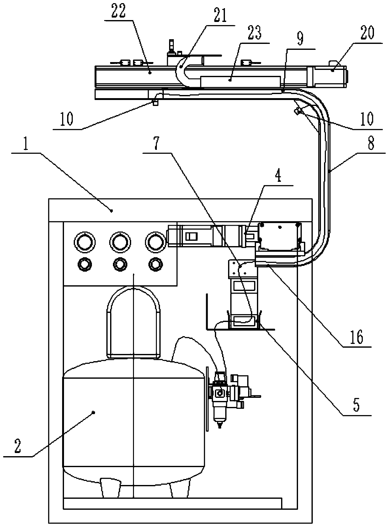
[0035] like figure 1 and 2 As shown, a paper deacidification equipment includes a worktable panel 1, a mounting cavity is provided at the bottom of the worktable panel 1, a stirring tank 17 and an air compressor 2 are arranged in the mounting cavity, and also includes a manipulator assembly and a blower diffuser. The manipulator assembly includes an X-axis manipulator running along the longitudinal direction of the worktable panel 1 provided at the lower part of the worktable panel 1, and an X-axis manipulator provided on the upper part of the worktable panel 1 along the broad side of the worktable panel 1. The Y-axis manipulator running in the direction and the U-shaped bracket for connecting the X-axis manipulator and the Y-axis manipulator are installed on the Y-axis manipulator. The blowing and diffusing device includes a gas control valve group 6, a gas pipe 7 and a gas nozzle 10. The gas nozzle 10 is installed on the Y-axis manipulator, one end of the gas pipe 7 is conn...
Embodiment 2
[0041] like figure 1 As shown, this embodiment is further optimized on the basis of Embodiment 1. This embodiment focuses on the improvements compared with Embodiment 1, and the similarities will not be repeated. In this embodiment, the X-axis manipulator It includes a first linear module 3, a first motor 4, a first drag chain 18 and a first chain slot 5. The first linear module 3 is installed on the lower part of the worktable panel 1, and the first motor 4 is connected to the first linear module. The line module 3 is connected, the first chain slot 5 is installed on the bracket below the first linear module 3, the first drag chain 18 is arranged in the first chain slot 5, and the bottom of the U-shaped bracket is fixed on the first straight line On the module 3, one end of the first drag chain 18 is fixed in the first chain groove 5, and the other end of the first drag chain 18 is connected to the bottom of the U-shaped bracket. The first linear module 3 is a belt linear mo...
Embodiment 3
[0046] like figure 2 As shown, this embodiment is further optimized on the basis of Embodiment 2. This embodiment focuses on the improvements compared with Embodiment 1, and the similarities will not be repeated. In this embodiment, the trachea 7 is sequentially Arranged in the first drag chain 18 , the first section rod 16 , the second section rod 8 and the third section rod 9 , the gas nozzle 10 is installed on the third section rod 9 .
[0047] Preferably, a first chamfer is provided at the connection between the first segment rod 16 and the second segment rod 8 , and a second chamfer is provided at the connection between the second segment rod 8 and the third segment rod 9 , a gas shower head 10 is installed at the second chamfered corner, and there is a certain angle between the gas shower head 10 at the second chamfered corner and the workbench panel 1 . The arrangement of the first chamfer and the second chamfer can prevent the trachea 7 and the infusion tube at the c...
PUM
 Abstract
Description
Claims
Application Information
 - R&D
- Intellectual Property
- Life Sciences
- Materials
- Tech Scout
- Unparalleled Data Quality
- Higher Quality Content
- 60% Fewer Hallucinations
Browse by: Latest US Patents, China's latest patents, Technical Efficacy Thesaurus, Application Domain, Technology Topic, Popular Technical Reports.
© 2025 PatSnap. All rights reserved.Legal|Privacy policy|Modern Slavery Act Transparency Statement|Sitemap|About US| Contact US: help@patsnap.com