Printing clamp for printing circuit substrate

A technology of printed circuit substrates and fixtures, which is applied in the directions of printed circuits, printed circuit manufacturing, and assembly of printed circuits with electrical components. The effect of ink adhesion

Inactive Publication Date: 2008-11-26
NIPPON MEKTRON LTD
View PDF4 Cites 0 Cited by
  • Summary
  • Abstract
  • Description
  • Claims
  • Application Information

AI Technical Summary

Problems solved by technology

[0007] 3. The suction hole of the printing head is blocked.
[0011] However, in substrates made of soft materials such as flexible printed circuit boards, there is a disadvantage that the substrate is warped and printing cannot be performed.

Method used


Image

  • Printing clamp for printing circuit substrate
  • Printing clamp for printing circuit substrate
  • Printing clamp for printing circuit substrate

Examples


Embodiment Construction

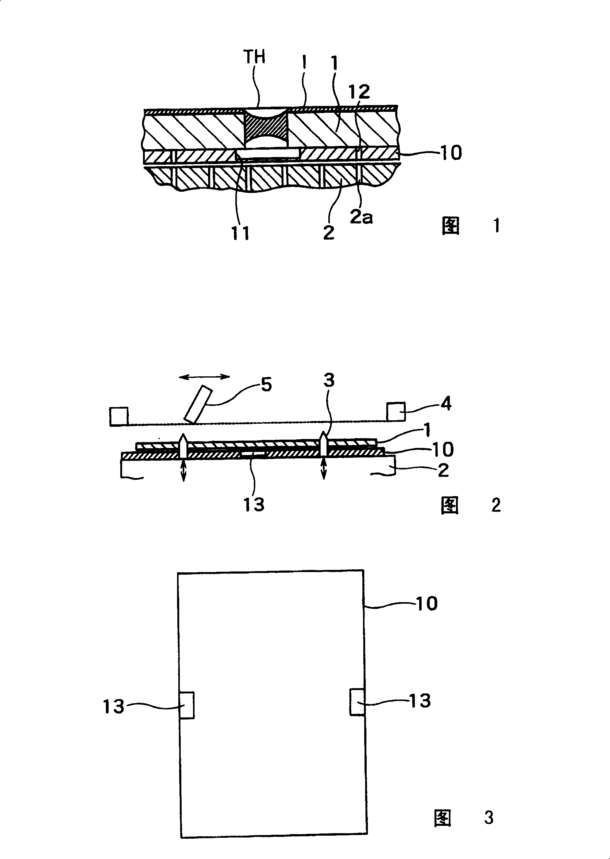
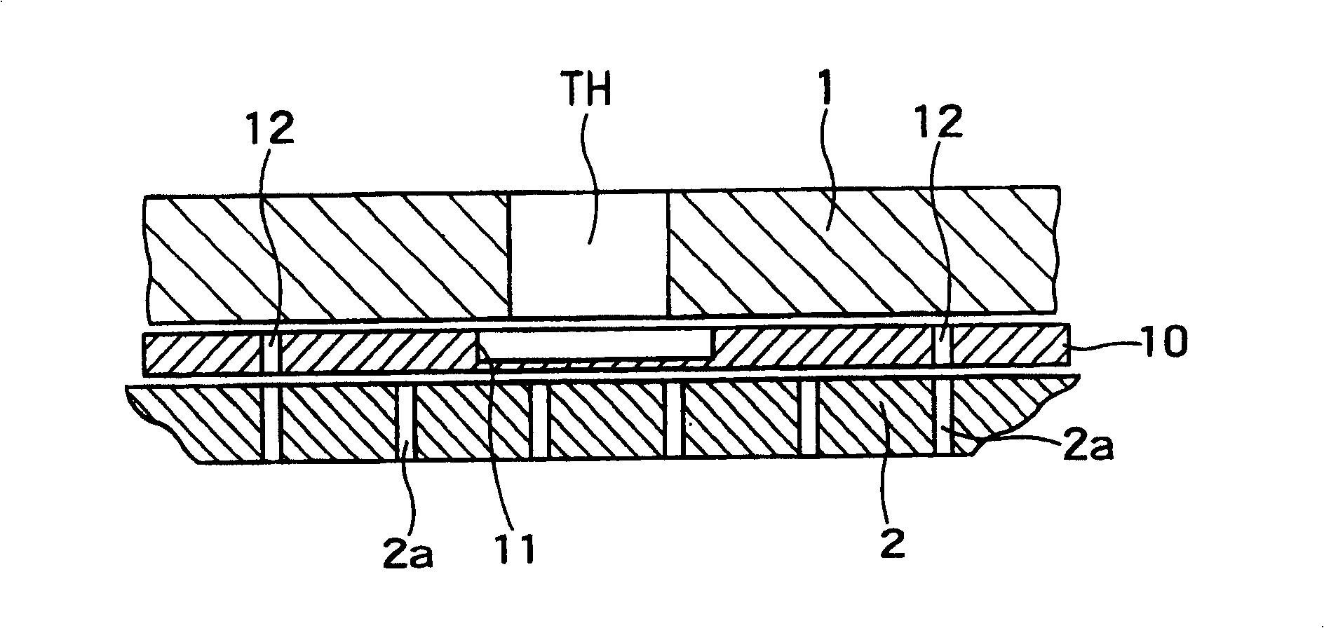
[0020] Fig. 1 is an explanatory diagram showing the installation of the printing jig of the present invention. Fig. 1 shows a cross-sectional view of the printed circuit board 1 placed on the printing machine head 2 by inserting the printing jig 10, which is an embodiment of the present invention. status.

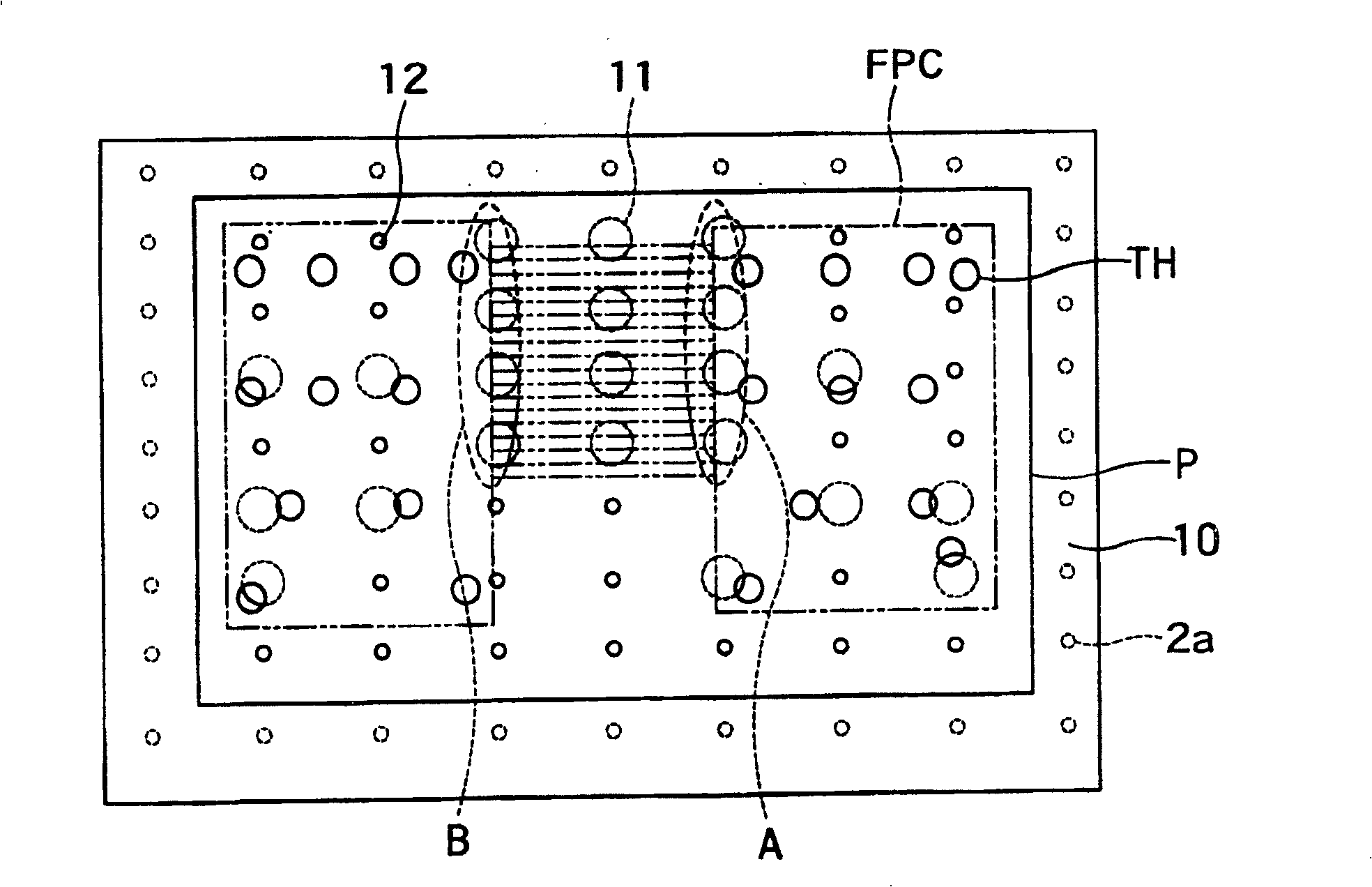
[0021] As shown in the figure, it is in a state where ink I adheres to the vicinity of the through hole TH and blocks the through hole TH. Also, a spot facing as a non-through hole is provided in the printing jig 10 directly below the through hole TH. A hole 11 is formed to form an ink receiving part. A through hole 12 is provided in the printing jig 10 at a position deviated directly below the through hole TH, which communicates with the suction hole 2a of the printing head 2.

[0022] Thus, if the printed circuit board 1 is sucked by vacuum suction by the printing head, the printed circuit board 1 is sucked through the through hole 12 of the printing jig 10. At this time,...


PUM


Abstract

Provided is a printing tool capable of preventing solder resist ink from creeping in the rear of a substrate even in the substrate made of a soft material. In the printing tool, the printed circuit board is retained on a printer bed to perform printing by fixing the printed circuit board to the printer bed. The printing tool (10) is flat and is inserted between the printer bed and the printed circuit board. In the printing tool for the printed circuit board, a non-through hole (11) is provided at a position corresponding to the through hole of the printed circuit board on a surface in contact with the printed circuit board, and a through hole (12) is provided in a region without any through holes.

Description

technical field [0001] The invention relates to a printing jig for a printed circuit board, in particular to a printing jig suitable for printing on a soft flexible printed circuit board. Background technique [0002] Generally speaking, except for the exposed parts such as pads, printed circuit boards are coated with solder etching ink to form a protective film. The coating of the solder etching ink is carried out by printing such as screen printing (refer to Japanese National Standard Kaiping Bulletin No. 6-191009). [0003] In order to perform this printing, the alignment guide pins provided on the printing head are inserted into the guide holes of the substrate to align the substrate, the substrate is fixed on the printing head by vacuum suction, and the printing plate and the substrate are aligned after lowering the guide pins. Contact for printing. [0004] In this case, sometimes etching ink flows into the back side through the through hole of the substrate due to t...

Claims


Application Information

Patent Timeline
Patent Type & Authority Patents(China)
IPC IPC(8): H05K3/12H05K3/00H05K3/34
Inventor 猪濑裕昭高桥正树濑川友和
Owner NIPPON MEKTRON LTD
Why Eureka
Try Eureka