Eureka AIR delivers breakthrough ideas for toughest innovation challenges, trusted by R&D personnel around the world.

Vertical film covering device based on V-method casting mold

A casting mold and film-covering device technology, applied in the field of mold casting, can solve problems such as damage, film pulling, and affecting work efficiency, and achieve reliable and uniform force, reliable adsorption and fixation, and improve casting efficiency.

Inactive Publication Date: 2022-03-15
梅州华和精密工业有限公司
View PDF0 Cites 0 Cited by
  • Summary
  • Abstract
  • Description
  • Claims
  • Application Information

AI Technical Summary

Problems solved by technology

[0003] In the V-method casting process, covering the model is the initial and relatively important part. The V-method casting film-coating device in the prior art lacks a device that can store the film. On the side of the membrane device, one is that the film is not well protected and is easily polluted, and the other is that it is inconvenient for workers to quickly lay the film on the bottom of the film frame, which affects work efficiency; in addition, the V method of the prior art casting film The laminating frame and heating box (or heating plate) of the device are designed to be separated. When preheating the film, the laminating frame and the heating box are attached so that the film can be fully and uniformly heated. After the film is heated, The laminating frame is separated from the heating box and covers the model with the film, but the film is easily bonded to the heating box during the heating process, and the film is easily pulled during the process of separating the film from the heating box by the laminating frame, resulting in A large degree of deformation or damage occurs in some areas of the film, resulting in the scrapping of the film

Method used


Image

  • Vertical film covering device based on V-method casting mold
  • Vertical film covering device based on V-method casting mold
  • Vertical film covering device based on V-method casting mold

Examples


Embodiment Construction

[0027] The present invention will be further described below in conjunction with the accompanying drawings and embodiments.

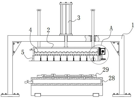
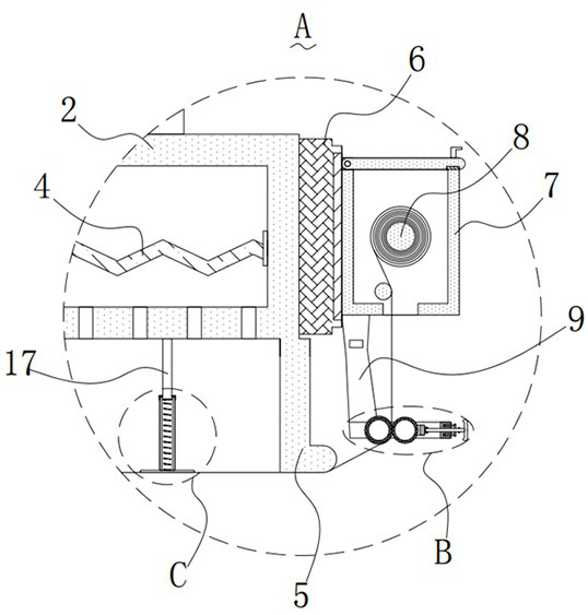
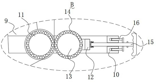
[0028] Please refer to Figure 1-Figure 7 , in this embodiment, the vertical coating device based on the V method casting mold includes a gantry 1, a heating box 2 is slidably installed on the top inner wall of the gantry 1, and a hydraulic cylinder 3 is fixedly installed on the top of the gantry 1 , the output shaft of the hydraulic cylinder 3 extends into the gantry 1 and is fixedly connected with the heating box 2, and the heating box 2 is fixedly installed with an electric heating wire 4, and the electric heating wire 4 is used to preheat the film to soften and heat the film. The bottom of the box 2 is integrally formed with a film-coated frame 5, the film-covered frame 5 is connected to the heating box 2, and a heat insulation board 6 is fixedly installed on one side of the heating box 2, and a mounting plate is embedded and fixed in the heat insul...


PUM


Abstract

The invention provides a vertical film covering device based on a V-method casting mold. The vertical film laminating device based on the V-method casting mold comprises a portal frame, a heating box is slidably installed on the inner wall of the top of the portal frame, a hydraulic cylinder is fixedly installed at the top of the portal frame, an output shaft of the hydraulic cylinder extends into the portal frame and is fixedly connected with the heating box, and an electric heating wire is fixedly installed in the heating box; a film covering frame is integrally formed at the bottom of the heating box, a heat insulation plate is fixedly mounted on the outer wall of one side of the heating box, a protection box is fixedly mounted on the outer wall of one side of the heat insulation plate, a film roller is rotatably mounted in the protection box, and two suspension arms are fixedly mounted at the bottom of the protection box. The vertical film laminating device based on the V-method casting mold has the advantages that the vertical film laminating device is provided with a film storage structure, related workers can conveniently and rapidly lay a film at the bottom of the film laminating frame on site, and the film is not prone to deformation and damage.

Description

technical field [0001] The invention relates to the technical field of mold casting, in particular to a vertical film coating device based on a V-method casting mold. Background technique [0002] V-method casting is a vacuum-sealed molding method, also known as negative pressure molding method. It uses plastic film to evacuate dry sand to form it. Since no adhesive is used, sand falling is simple, so the consumption of molding materials can be reduced to a minimum. It is very low, and it can also reduce waste sand and improve the surface quality and dimensional accuracy of castings. [0003] In the V-method casting process, covering the model is the initial and relatively important part. The V-method casting film-coating device in the prior art lacks a device that can store the film. On the side of the membrane device, one is that the film is not well protected and is easily polluted, and the other is that it is inconvenient for workers to quickly lay the film on the bot...

Claims


Application Information

Patent Timeline
Patent Type & Authority Applications(China)
IPC IPC(8): B22C9/03
CPCB22C9/03
Inventor 蔡风华陈海良蔡立华蔡炀
Owner 梅州华和精密工业有限公司
Why Eureka
Eureka Blog
Learn More