
Passivation method and device for sliced battery, sliced battery and photovoltaic module

A slicing and battery technology, applied in photovoltaic power generation, electrical components, circuits, etc., can solve problems such as limiting the progress of photovoltaic module development, photovoltaic module power loss, and slicing battery efficiency loss, etc., to improve photoelectric efficiency, good photoelectric efficiency, The effect of good photoelectric conversion efficiency

Active Publication Date: 2019-08-16
LONGI SOLAR TECH (TAIZHOU) CO LTD
View PDF7 Cites 10 Cited by
  • Summary
  • Abstract
  • Description
  • Claims
  • Application Information

AI Technical Summary

Problems solved by technology

[0004] However, with the in-depth research on laser slicing, it was found that although the problem of power loss of photovoltaic modules was solved, the problem of efficiency loss of sliced ​​cells was introduced.
According to reports, the efficiency of conventional passivated emitter and rear cells (PERC cells) after halving is reduced by about 0.1%, and the efficiency of intrinsic thin-film heterojunction cells (HIT cells) is reduced by 0.4% after halving.
The large loss of cutting efficiency severely limits the progress of photovoltaic module technology to half-cut and shingled technology

Method used


Image

  • Passivation method and device for sliced battery, sliced battery and photovoltaic module
  • Passivation method and device for sliced battery, sliced battery and photovoltaic module
  • Passivation method and device for sliced battery, sliced battery and photovoltaic module

Examples


Embodiment 1

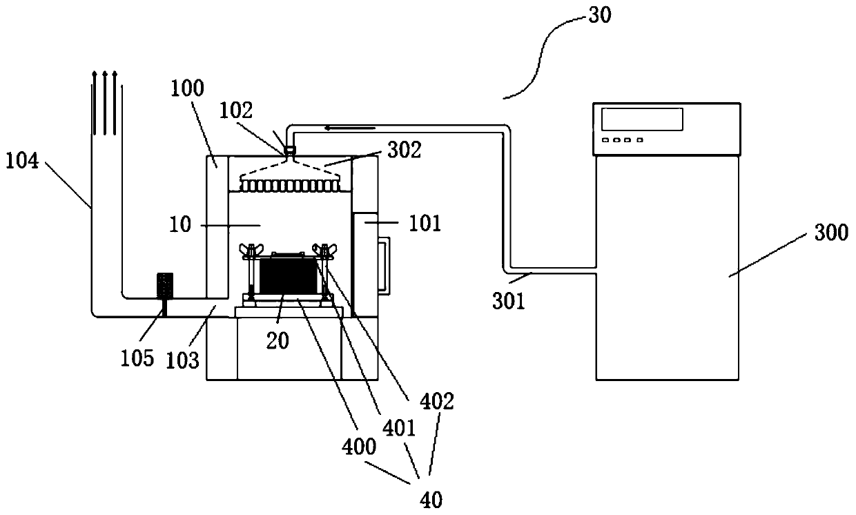
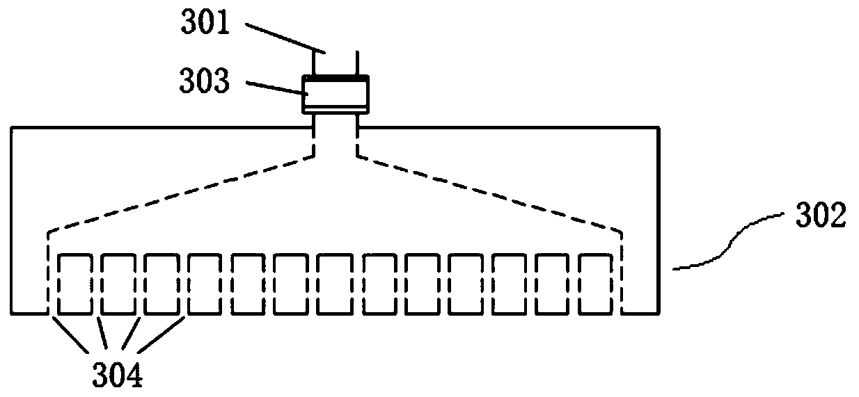
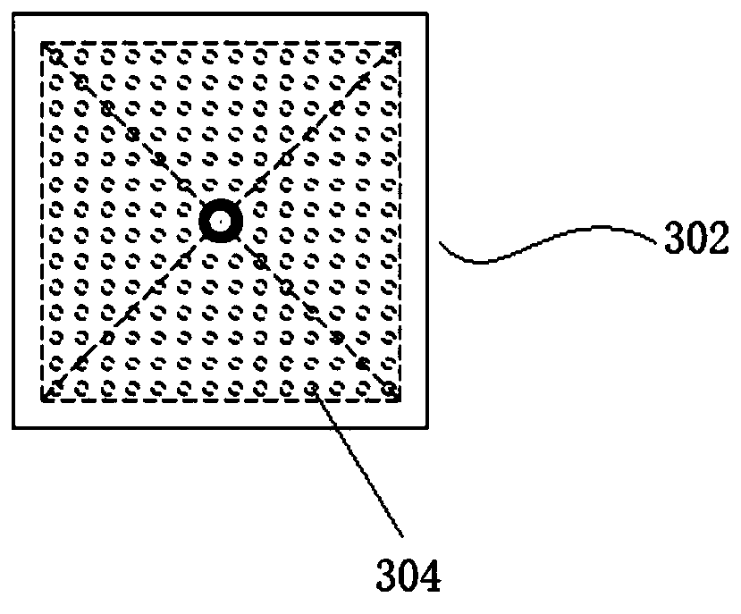
[0074] S100, take 5 busbar half-cut patterned HIT cells and stack them sequentially between the carrier plate 400 and the cover plate 401 (for details, refer tofigure 1 ), placed in the box body 100, close the box door 101, close the pneumatic valve 105 on the exhaust pipeline 104, set the parameters of the ozone generator 300, and open the ozone generator 300 so that the output volume concentration is 150 Ozone at a rate of 10,000 is sprayed into the box body 100 for 90 seconds at a flow rate of 1 liter / min through the pipeline 301, the adapter 303 and the nozzle 302;

[0075] S101. Turn off the ozone generator 300, open the pneumatic valve 105, and open the box door 101 after the ozone in the box body 100 is emptied.

[0076] The obtained sliced ​​battery is denoted as A1.

Embodiment 2

[0078] S100. Stack and clamp 5 busbar half-cut PERC cells sequentially between the carrier plate 400 and the cover plate 401 (for details, refer to figure 1 ), placed in the box body 100, close the box door 101, close the pneumatic valve 105 on the exhaust pipeline 104, set the parameters of the ozone generator 300, and open the ozone generator 300 so that the output volume concentration is 150 Ozone at a rate of 10,000 is sprayed into the box body 100 for 90 seconds at a flow rate of 1 liter / min through the pipeline 301, the adapter 303 and the nozzle 302;

[0079] S101. Turn off the ozone generator 300, open the pneumatic valve 105, and open the box door 101 after the ozone in the box body 100 is emptied.

[0080] The obtained sliced ​​battery is denoted as A2.


PUM


Abstract

The invention provides a passivation method for a sliced battery, comprising the steps of: performing an ozonization treatment on the fracture surface of the sliced battery, wherein the ozonization treatment includes: spraying an ozone-containing passivation gas onto the fracture surface of the sliced battery at room temperature. There is also provided a passivation device for the sliced battery,comprising a passivation chamber capable of accommodating at least one sliced battery, and an ozone spraying unit for spraying the passivation gas onto the fracture surface of the sliced battery. A battery slice obtained by using the passivation method and a photovoltaic module composed of the battery slice are also provided. The passivation method and device can form a silicon dioxide protectivelayer on the fracture surface of the sliced battery to avoid recombination of photo-generated carriers on the fracture surface, thereby greatly improving the photoelectric efficiency of the sliced battery.

Description

technical field [0001] The invention relates to the technical field of photovoltaic sliced ​​batteries, in particular to a passivation method and device for sliced ​​batteries, sliced ​​batteries and photovoltaic modules. Background technique [0002] In recent years, photovoltaic technology has developed very rapidly, and the conversion efficiency of industrialized high-efficiency crystalline silicon cells has increased by about 0.5% absolute efficiency per year. With the improvement of the efficiency of crystalline silicon cells, the current density of crystalline silicon cells has also increased, and has exceeded 40.3 mA / cm2. As the current density of crystalline silicon cells rises sharply, the current of the entire cell also increases significantly, resulting in high power loss in the traditional way of photovoltaic modules formed by electrical interconnection of entire cells. [0003] With the rapid development of laser technology, laser slicing has become a very econ...

Claims


Application Information

Patent Timeline
IPC IPC(8): H01L31/0216H01L31/18
CPCH01L31/1868H01L31/02167Y02E10/50Y02P70/50
Inventor 王建波张琦忠朱琛吕俊
Owner LONGI SOLAR TECH (TAIZHOU) CO LTD
Learn More