A pcb rogowski coil for measuring the chip current of crimping igbt module

A technology of Rogowski coils and measuring coils, which is applied in the directions of measuring current/voltage, measuring electrical variables, transformer/inductor coils/windings/connections, etc. It can solve the problem of only measuring distribution at the edge, chip current cannot be measured, and increasing current Measurement cost and other issues, to achieve the effect of ensuring the accuracy of current measurement, facilitating research, and eliminating electromagnetic interference

Active Publication Date: 2020-07-10
HUAZHONG UNIV OF SCI & TECH
View PDF5 Cites 0 Cited by
  • Summary
  • Abstract
  • Description
  • Claims
  • Application Information

AI Technical Summary

Problems solved by technology

[0004] However, in addition to the front-end measurement coil, this flexible current probe also needs a thicker and longer wire to lead out the measurement signal, and the number of IGBT module chips is large and the spacing is small, so this method can only measure the internal distribution of the crimped IGBT module. chip at the edge, chip current cannot be measured elsewhere
In addition, when the number of measured boss branches increases, the number of devices needs to be increased accordingly. Since the flexible current probe is a precision device, the cost of current measurement is greatly increased
[0005] Generally speaking, the existing precision measurement equipment has many leads and complicated operation when measuring the chip current of the IGBT module, and can only measure the chip current distributed at the edge

Method used


Image

  • A pcb rogowski coil for measuring the chip current of crimping igbt module
  • A pcb rogowski coil for measuring the chip current of crimping igbt module
  • A pcb rogowski coil for measuring the chip current of crimping igbt module

Examples


Embodiment Construction

[0028] In order to make the object, technical solution and advantages of the present invention clearer, the present invention will be further described in detail below in conjunction with the accompanying drawings and embodiments. It should be understood that the specific embodiments described here are only used to explain the present invention, not to limit the present invention.

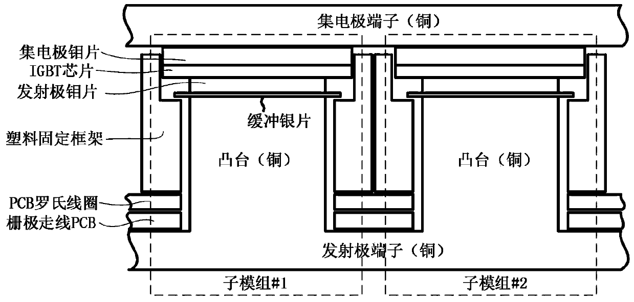
[0029] The collector molybdenum sheet, IGBT chip, emitter molybdenum sheet, silver sheet boss and plastic fixing frame in the crimping IGBT module are collectively referred to as sub-modules as a subunit. figure 1 A cross-sectional view of two sub-modules of a crimped IGBT module is shown. The upper and lower layers of molybdenum sheets can maintain uniform contact pressure on both sides and reduce the thermal expansion of the IGBT chip at high temperature, and as a good conductor of electricity and heat, it can conduct current and device loss well. The buffer silver sheet can well alleviate the t...


PUM

PropertyMeasurementUnit
widthaaaaaaaaaa

Abstract

The invention discloses a PCB Rogowski coil for measuring a chip current of a pressure-welding IGBT module. The PCB Rogowski coil comprises a circular PCB base plate, boss penetrating holes and measuring coils, the multiple boss penetrating holes are distributed on the circular PCB base plate, distribution positions and sizes correspond to boss structures in the pressure-welding IGBT module, the measuring coils form multi-turn coil structures uniformly distributed around the boss penetrating holes through upper and lower routings and through holes of the circular PCB base plate, the PCB Rogowski coil is embedded between the boss structures in the pressure-welding IGBT module and superposed on a grid electrode routing PCB in the pressure-welding IGBT module, and when a changing current flows through a boss branch circuit, an induction potential is generated at the corresponding measuring coil, and the current change of the boss branch circuit is obtained through integral conversion of the induction potential. According to the PCB Rogowski coil, the current of the branch circuit at any position can be measured, the measuring precision of the current is improved, the operation is simple, and the current measuring cost of the parallel-connected branch circuits of the pressure-welding IGBT module is greatly reduced.

Description

technical field [0001] The invention belongs to the technical field of current measurement, and more specifically relates to a PCB Rogowski coil for measuring the current of a crimped IGBT module chip. Background technique [0002] The main packaging forms of high-power IGBT (Insulated Gate Bipolar Transistor, insulated gate bipolar transistor) modules are soldered package and crimped package. Compared with soldered package, the output power of crimped package module is higher, and the pressure The junction package has the advantages of double-sided heat dissipation and low parasitic inductance, and is more suitable for application in converter valves and circuit breakers. The distribution position and stress distribution of each chip in the crimping package module are inconsistent, so the parasitic inductance and contact resistance of each branch are different, resulting in different degrees of dispersion of current between chips. The branch with small parasitic inductance...

Claims


Application Information

Patent Timeline
Patent Type & Authority Patents(China)
IPC IPC(8): G01R19/00H01F27/28H01F38/24
CPCG01R19/00H01F27/2804H01F38/24
Inventor 梁琳韩鲁斌
Owner HUAZHONG UNIV OF SCI & TECH
Why Eureka
Try Eureka