
Stress, temperature and vibration composite detection optical fiber sensor and signal processing method

A fiber optic sensor and composite detection technology, applied in the direction of converting sensor output, using optical devices to transmit sensing components, instruments, etc., can solve problems such as system errors, optical fiber physical quantities are not completely the same, and dynamic vibration signals cannot be detected, so as to reduce errors. High reporting rate, low noise level and high positioning accuracy

Active Publication Date: 2019-08-16
SHANTOU UNIV
View PDF6 Cites 16 Cited by
  • Summary
  • Abstract
  • Description
  • Claims
  • Application Information

AI Technical Summary

Problems solved by technology

But BOTDA can only detect static strain and cannot detect dynamic vibration signals
[0006] Existing optical fiber sensors can only measure one of vibration, stress or temperature. If the above physical quantities are to be measured at the same time, multiple sensing optical fibers need to be laid. The physical quantities felt by each optical fiber are not exactly the same, which will introduce system errors.

Method used


Image

  • Stress, temperature and vibration composite detection optical fiber sensor and signal processing method
  • Stress, temperature and vibration composite detection optical fiber sensor and signal processing method
  • Stress, temperature and vibration composite detection optical fiber sensor and signal processing method

Examples


Embodiment Construction

[0041] In order to make the object, technical solution and advantages of the present invention clearer, the present invention will be further described in detail below in conjunction with the accompanying drawings.

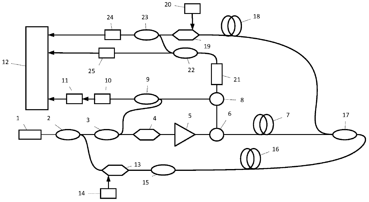
[0042] Such as figure 1, a stress, temperature and vibration composite detection optical fiber sensor according to an embodiment of the present invention, comprising a laser light source 1, a first 1:1 coupler 2, a 1:99 coupler 3, an acousto-optic modulator 4, and an erbium-doped fiber amplifier 5 , the first circulator 6, the sensing fiber 7, the second circulator 8, the second 1:1 coupler 9, the first photodetector 10, the down conversion filter circuit 11, the data acquisition system and the upper computer 12, the first Electro-optic modulator 13, first microwave generator 14, fiber isolator 15, auxiliary fiber 16, third 1:1 coupler 17, reference fiber 18, second electro-optic modulator 19, second microwave generator 20, filter grating 21. A fourth 1:1 coupler...


PUM


Abstract

Embodiments of the invention disclose a stress, temperature and vibration composite detection optical fiber sensor and a signal processing method. Laser light is divided into two beams; a part of thefirst beam of light is taken as local oscillator light, and the rest part is incident from the head end of a sensing optical fiber after passing through an acousto-optic modulator; after the second beam of light is subjected to frequency conversion by an electrooptical modulator, a part of the second beam of light is incident from the tail end of the sensing optical fiber, and the other part is used as reference light to be incident to a reference optical fiber; at the head end of the sensing optical fiber, the light transmitted backwards passes through a filtering raster, wherein reflected light and the local oscillator light interfere with each other, and after being detected, the reflected light is collected as a signal 1 through frequency reduction demodulation; a part of the transmitted light is directly detected and collected as a signal 2, and the other part interferes with the reference light and then is detected and collected as a signal 3; and envelope denoising is carried out on the signal 1, a vibration position is obtained by using a wavelet information entropy algorithm, the signal 2 is fitted to obtain stress or temperature distribution, envelope denoising is carriedout on the signal 3, and a vibration frequency is obtained through Fourier transform.

Description

technical field [0001] The invention relates to the field of optical fiber sensing, in particular to an optical fiber sensor for composite detection of stress, temperature and vibration and a signal processing method. Background technique [0002] Due to its high sensitivity, high positioning accuracy, and electromagnetic immunity, the distributed optical fiber sensing system is widely used in long-distance oil and gas pipeline monitoring, perimeter security, building structure health monitoring and other fields. [0003] The Mach-Zehnder Interferometer (MZI) distributed optical fiber sensing system, through interference, changes the optical phase difference caused by external disturbances in the sensing optical path into light intensity changes, thereby realizing vibration detection. In the dual MZI system, the vibration can be located by the correlation time delay estimation method, but the positioning accuracy of this method is low due to the large uncertainty of the calc...

Claims


Application Information

Patent Timeline
IPC IPC(8): G01D5/353
CPCG01D5/35329G01D5/35354G01D5/35364
Inventor 施羿王原野赵雷范衠
Owner SHANTOU UNIV
Learn More