
Metal mesh and mesh rack plastic-dipping heating furnace

A metal mesh and heating furnace technology, which is applied in the direction of pretreatment surface, coating, device for coating liquid on the surface, etc. and other problems, to achieve the effect of rapid and uniform heat distribution, better heating effect, and convenient heating work.

Inactive Publication Date: 2019-08-16
徐州万佳机电设备制造有限公司
View PDF4 Cites 3 Cited by
  • Summary
  • Abstract
  • Description
  • Claims
  • Application Information

AI Technical Summary

Problems solved by technology

[0005] 1. The heating wire is used for heating, and the heat dissipated from the heating wire cannot be quickly and evenly transferred to the upper and lower parts of the heating device; 2. The metal mesh is directly placed on the placement plate, and the heat transfer is relatively slow in the form of heat conduction
[0006] Therefore, the problems of uneven heat transfer and slow heat transfer of heat conduction when the metal mesh grid is heated need to be solved urgently.

Method used


Image

  • Metal mesh and mesh rack plastic-dipping heating furnace
  • Metal mesh and mesh rack plastic-dipping heating furnace
  • Metal mesh and mesh rack plastic-dipping heating furnace

Examples


Embodiment 1

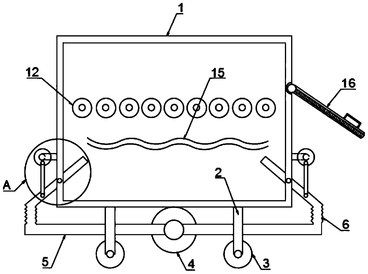
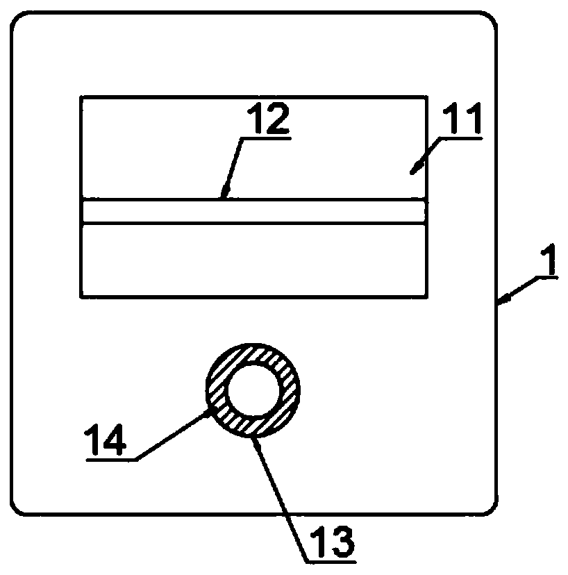
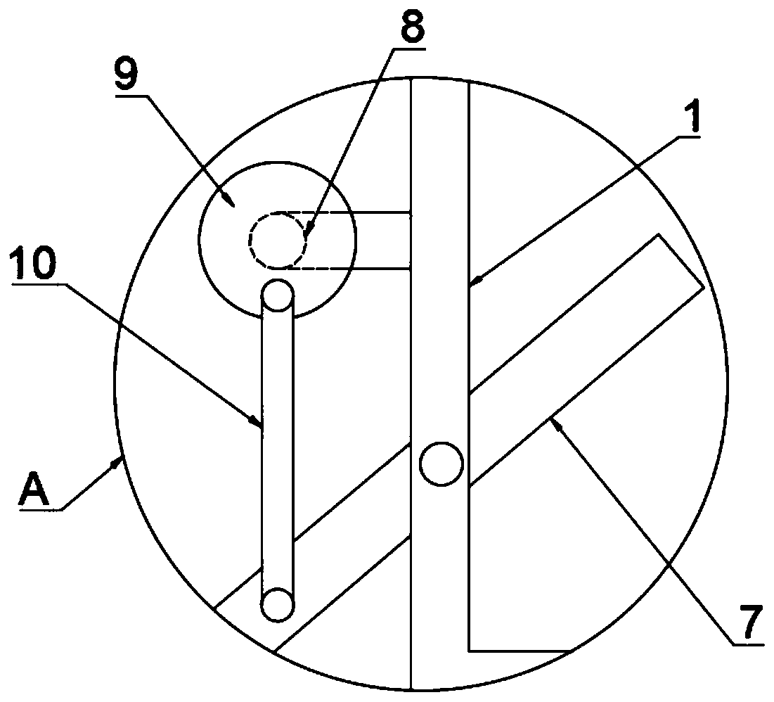
[0031] refer to Figure 1-3 , a kind of metal mesh grid frame dipping heating furnace, comprising a furnace body 1, a plurality of support legs 2 are fixedly connected to the lower side wall of the furnace body 1, and a roller 3 is arranged at the lower end of each support leg 2, and the roller 3 To move the furnace body 1, a feed inlet 11 is provided on one side wall of the furnace body 1, and a placement device and a plurality of heating wires 15 are arranged between the inner walls of both sides of the furnace body 1. 1 A plurality of rollers 12 between the inner walls on both sides, the plurality of rollers 12 are located above the heating wire 15, the heating wire 15 heats the air in the furnace body 1, and the heated air passes through the gap between the rollers 12 upwards It contacts with the metal mesh to realize the uniform distribution of the airflow and complete the heating of the metal mesh. The inner wall of the feed port 11 is connected with the door plate 16 th...

Embodiment 2

[0035] refer to Figure 4 , a kind of metal mesh frame dipping heating furnace, comprising a furnace body 1, the lower side wall of the furnace body 1 is fixedly connected with a plurality of support legs 2, the lower end of each support leg 2 is provided with a roller 3, through the roller 3 To move the furnace body 1, a feed port 11 is provided on one side wall of the furnace body 1, a placement device and a plurality of heating wires 15 are arranged between the inner walls of both sides of the furnace body 1, and the placement device is fixed on the furnace body 1 The intubation tubes on the inner walls of both sides are vertically inserted with an insertion rod, and the outer wall of the insertion rod is fixed with a horizontally arranged supporting plate 17, and two U-shaped rods 18 are inserted on the outer side of the furnace body 1, two U-shaped bar 18 is positioned at one end in body of heater 1 and is fixed with splint 19, and the upper side wall of body of heater 1 ...


PUM


Abstract

The invention belongs to the technical field of plastic-dipping heating furnaces, and particularly relates to a metal mesh and mesh rack plastic-dipping heating furnace. Aiming at the problem that heat transfer is not uniform and heat transfer through heat conduction is slow in an existing metal mesh and mesh rack heating process, and according to the following scheme, the plastic-dipping heatingfurnace comprises a furnace body, wherein a plurality of supporting legs are fixedly connected to the lower side wall of the furnace body, a rolling wheel is arranged at the lower end of each supporting leg, a material feeding hole is formed in the side wall of one side of the furnace body, a placing device and a plurality of heating wires are arranged between the inner walls of the two sides of the furnace body, a door plate matched with the material feeding hole is rotationally connected to the inner wall of the material feeding hole, and a convection mechanism is arranged on the lower sideof the furnace body. According to the metal mesh and mesh rack plastic-dipping heating furnace, the convection mechanism is arranged on the lower side of the furnace body, through the swinging of a gas outlet pipe and the leading-out of gas in the gas outlet pipe, the flow of the gas in the furnace body is accelerated, heat in the furnace body is uniformly distributed, the heat is directly transmitted out to heat a metal mesh, and the heating effect is better.

Description

technical field [0001] The invention relates to the technical field of plastic dipping heating furnaces, in particular to a plastic dipping heating furnace for metal mesh grids. Background technique [0002] As a filter or support, metal mesh is widely used in daily life. Metal mesh is generally made of different numbers of metal mesh and support mesh combined with edge wrapping process. [0003] After the metal mesh is produced, it needs to be dipped in plastic. Most of the liquid dipping process uses thermoplastic dipping liquid. The thermoplastic coating film has the characteristics of preheating and softening, and can be solidified to form a film after cooling. The main physical The process of permanent melt plasticization and film formation is relatively simple in processing and production. At present, the most typical and commonly used is polyvinyl chloride dipping solution, which is a synthetic raw material mixed with polyvinyl chloride with more than 10 kinds of adv...

Claims


Application Information

Patent Timeline
Patent Type & Authority Applications(China)
IPC IPC(8): B05D3/04B05C9/14
CPCB05C9/14B05D3/0413
Inventor 刘尊礼
Owner 徐州万佳机电设备制造有限公司
Learn More