Vortex tube for mass spectrometry reaction acceleration and signal enhancement and its realization method

A vortex tube and mass spectrometry technology, applied in the field of ion optical device fabrication, can solve the problems of low ion mixing contact efficiency, difficult to adjust reaction time, low ion transmission efficiency, etc. The effect of improving reaction efficiency

Active Publication Date: 2021-02-02
INST OF CHEM CHINESE ACAD OF SCI
View PDF2 Cites 1 Cited by
  • Summary
  • Abstract
  • Description
  • Claims
  • Application Information

AI Technical Summary

Problems solved by technology

[0005] In view of the above analysis, the present invention aims to provide a vortex tube for mass spectrometry reaction acceleration and signal enhancement and its implementation method, in order to solve the problems of low ion transmission efficiency and ionization in the reaction monitoring and reaction acceleration process of existing mass spectrometry. Low efficiency, low efficiency of reactant ion mixing and contact, and difficult adjustment of reaction time

Method used


Image

  • Vortex tube for mass spectrometry reaction acceleration and signal enhancement and its realization method
  • Vortex tube for mass spectrometry reaction acceleration and signal enhancement and its realization method
  • Vortex tube for mass spectrometry reaction acceleration and signal enhancement and its realization method

Examples


Embodiment 1

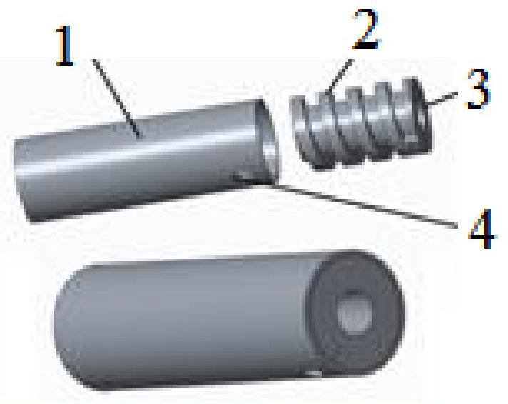
[0055] The vortex tube provided in this embodiment consists of two parts: a sealed tube and a threaded tube. The total length of the threaded pipe is 15.0mm, the maximum outer diameter is 10.0mm, the cross section of the thread is a rectangle of 2.0mm×1.5mm, and the pitch is 3.5mm. There is an ion channel with a diameter of 4.0mm in the center of the threaded tube. The length of the sealed tube is 30.0mm, the inner diameter is 10.1mm, and the outer diameter is 11.0mm, and a small hole with a diameter of 2.5mm is left at one end to introduce gas into the vortex tube. The threaded pipe is sleeved into the sealing pipe, and the two are tightly slidable, and one end of the threaded pipe is aligned with the end where the small air inlet hole on the sealing pipe is located. Gas is introduced through small holes and into the threaded grooves. Under the diversion action of the thread, the gas spirals forward, and after 15mm, it breaks away from the thread at the end of the threaded ...

Embodiment 2

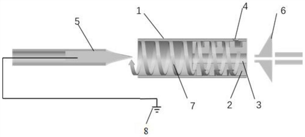
[0057] This embodiment provides a usage of the vortex tube of the present invention. Such as figure 2 As shown, the Nano-ESI ion source is placed on the front side of the vortex tube with its tip flush with the vortex tube outlet. The vortex tube is placed between the ion source and the MS inlet. After the sample is injected and a high voltage of 1000-5000V is provided by the high-voltage power supply 8, the tip of the Nano-ESI will generate many charged small droplets. Under the action of the vortex gas 7 for these small droplets, the solvent evaporates rapidly, and the volume of the droplets decreases. The reactants inside the droplet continue to accumulate on the surface of the droplet. When the surface tension of the droplet is exceeded, a "Coulomb explosion" occurs, and the droplet further becomes a smaller droplet. After several rounds of this process, charged ions are formed one by one in the vortex tube and finally enter the mass spectrometer to be detected. Durin...


PUM

PropertyMeasurementUnit
diameteraaaaaaaaaa
diameteraaaaaaaaaa
lengthaaaaaaaaaa

Abstract

The invention relates to a vortex tube used for mass spectrometry reaction acceleration and signal enhancement and its implementation method, which belongs to the technical field of ion optical devices and solves the problems of low ion transmission efficiency and low ion transmission efficiency in the process of mass spectrometry reaction monitoring and reaction acceleration in the prior art. The ionization efficiency is low, and the reactant ion mixing contact efficiency is low, and the reaction time is difficult to adjust. The vortex tube used for the mass spectrometry inlet includes a sealed tube and a threaded tube with an axial ion channel. The threaded tube has external threads and is placed in the sealed tube, and the groove of the external thread is used as a gas channel; the vortex tube is placed between the ion source and Between the mass spectrometer inlets; the side wall of the sealed tube is provided with a gas flow inlet for introducing gas. The method for enhancing the mass spectrometry signal includes placing the vortex tube→injecting the sample→introducing nitrogen gas→entering the mass spectrometry detection. The invention realizes enhancing the response signal of the mass spectrometer by arranging the vortex tube.

Description

technical field [0001] The invention relates to the technical field of manufacturing ion optical devices, in particular to a vortex tube used for mass spectrometry reaction acceleration and signal enhancement and a realization method. Background technique [0002] Mass spectrometry has high specificity, high sensitivity, high analysis speed, and certain structural characterization capabilities, so it is widely used in the field of reaction monitoring. People use mass spectrometry to track reaction progress, study reaction kinetics, screen catalysts, and elucidate reaction mechanisms by monitoring reaction intermediates. Electrospray ionization (ESI), nano-electrospray ionization (Nano-ESI) plasma sources have achieved success in the field of reaction monitoring. During reaction monitoring, it was found that the reactions taking place in the droplets ejected from the ESI plasma source were accelerated. The reaction that originally requires special conditions such as high te...

Claims


Application Information

Patent Timeline
Patent Type & Authority Patents(China)
IPC IPC(8): H01J49/04
CPCH01J49/04
Inventor 聂宗秀李玉泽王光辉熊彩侨
Owner INST OF CHEM CHINESE ACAD OF SCI
Why Eureka
Try Eureka