


Quick Research
Generate reliable direction feasibility study reports for your R&D in just a few steps.

Technical Q&A
Discover and master advanced knowledge NOW. Basics, ideas, possibilities, all at once.

Find Solutions
As an expert in R&D theories, this can generate solutions to your technical problems instantly.

Evaluate Feasibility
Analyze your overall solution with one click, know your potential R&D risks in advance.

Monitor Landscape
Get weekly tech updates, stay abreast of the latest tech innovations and key insights.
Vehicle braking device
A brake device and vehicle technology, applied in the direction of brake transmission device, brake action activation device, brake, etc., can solve the problems of increased number of components, increased cost, and large size
- Summary
- Abstract
- Description
- Claims
- Application Information
AI Technical Summary
Problems solved by technology
Method used
Image

Examples
no. 1 approach
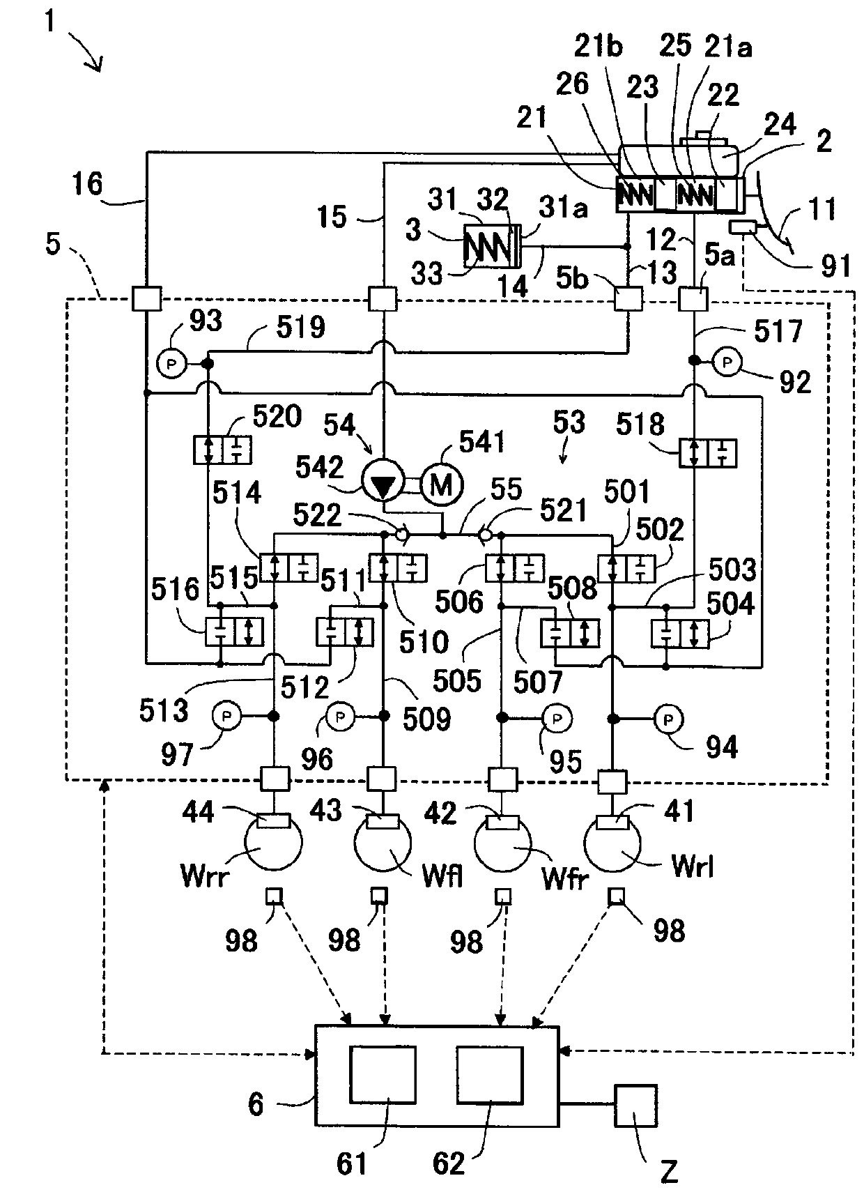
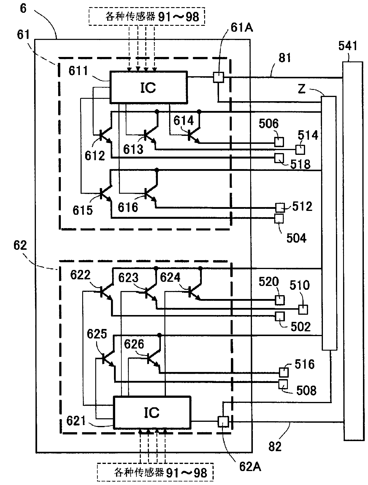
[0051] In this way, according to the first embodiment, even when any abnormality occurs in any one of the first drive circuit 61 and the second drive circuit 62, the three wheels W can be made to exhibit the same braking force as in the normal state. The wheels W exert a braking force based on the line pressure. Furthermore, according to the first embodiment, the power supply unit and the coil of the solenoid valve are not duplicated, but only the drive circuit is mainly added, so that the increase in the number of parts and the accompanying increase in size and cost can be suppressed. In other words, according to the first embodiment, while suppressing an increase in the number of parts, fail-safe performance at the time of an abnormality can be improved. According to the first embodiment, for example, existing structures can be utilized for the components of the actuator 5 .
[0052] In addition, the vehicle brake device 1 according to the first embodiment includes a first ...
no. 2 approach >
[0055] Compared with the first embodiment, the vehicle brake device 10 of the second embodiment is mainly different in that it includes a third control valve and a fourth control valve. Therefore, the different parts will be described. In the description of the second embodiment, the description of the first embodiment and the drawings can be referred to.
[0056] Such as Figure 4 As shown, the hydraulic flow path portion 53A of the second embodiment further includes a third control valve 523 and a fourth control valve 524 in addition to the configuration of the hydraulic flow path portion 53 of the first embodiment. The third control valve 523 is a solenoid valve (a normally open solenoid valve) that opens in a non-energized state and is arranged in series with the first control valve 518 in the first main passage 517 . The third control valve 523 can be said to be connected in series with the first control valve 518 . In the first main flow path 517 , the third control v...
no. 3 approach >
[0066] Compared with the first embodiment, the vehicle braking device of the third embodiment differs in the connection structure between the first control valve 518 and the second control valve 520 and the first drive circuit 61 and the second drive circuit 62 . Therefore, the different parts will be described. In the description of the third embodiment, the description of the first embodiment and the drawings can be referred to.
[0067] Such as Figure 5 As shown, the first control valve 518 and the second control valve 520 of the third embodiment are respectively connected to the first drive circuit 61 and the second drive circuit 61 and the second drive circuit 62 so as to be independently controllable. Circuit 62. The first drive circuit 61 is connected to the first control valve 518 via a wire 83 , and is connected to the second control valve 520 via a wire 84 . The second drive circuit 62 is connected to the first control valve 518 via a wire 85 and is connected to...
PUM
 Abstract
Description
Claims
Application Information
 - R&D Engineer
- R&D Manager
- IP Professional
- Industry Leading Data Capabilities
- Powerful AI technology
- Patent DNA Extraction
Browse by: Latest US Patents, China's latest patents, Technical Efficacy Thesaurus, Application Domain, Technology Topic, Popular Technical Reports.
© 2024 PatSnap. All rights reserved.Legal|Privacy policy|Modern Slavery Act Transparency Statement|Sitemap|About US| Contact US: help@patsnap.com