Trunnion-type ball valve
A technology of ball valve and ball seat, which is applied in the field of assembly structure of ball seat and seat ring, can solve the problems of partial wear and sealing performance of the sealing surface, decline, etc., and achieve stable pressure relief point, improved processability and assembly, and high sealing performance Effect
Active Publication Date: 2017-08-29
KITZ CORP
View PDF10 Cites 2 Cited by
- Summary
- Abstract
- Description
- Claims
- Application Information
AI Technical Summary
Problems solved by technology
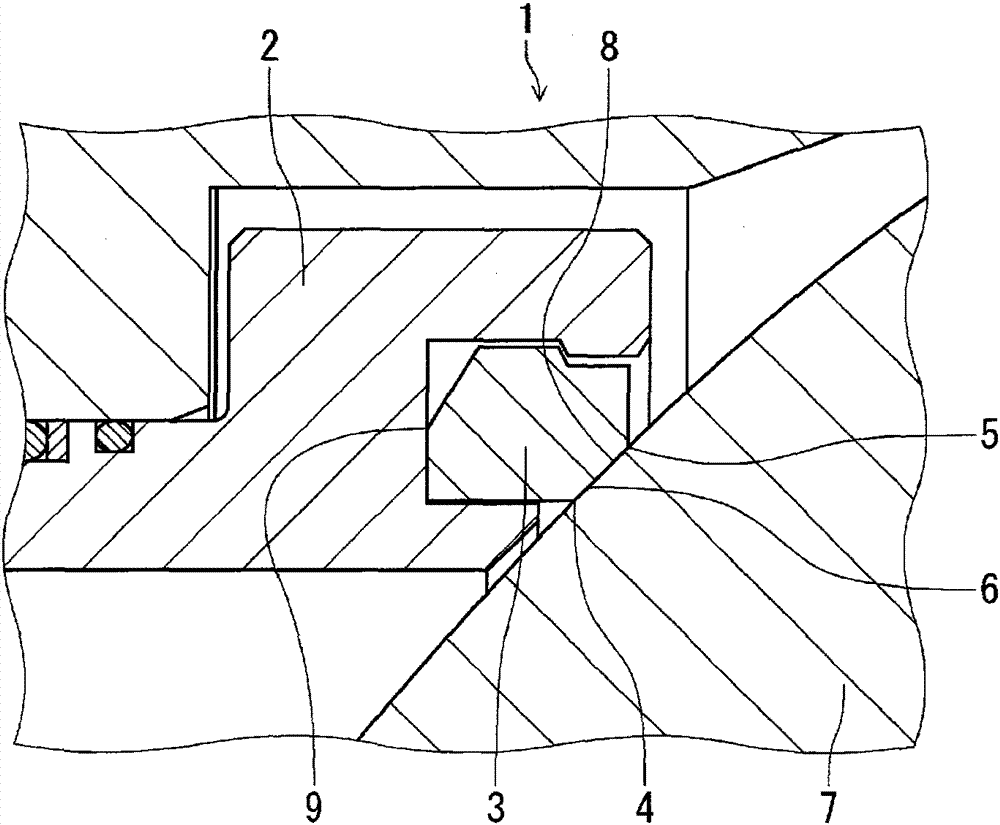
However, in either case, when the fluid is under high pressure, like the ball valve in Fig. 14, the ball seat elastically deforms in the opening direction, and the contact with the ball valve body changes from surface contact to linear contact approach, Partial wear may occur on the sealing surface and the sealing performance will decrease
Method used
View moreImage
Smart ImageViewing Examples

Examples
Embodiment Construction
Login to View More PUM
 Abstract
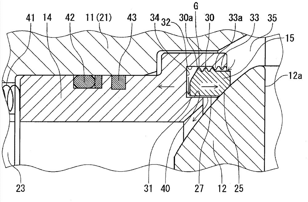
A seat retainer (14) fitted with a ball seat (15) is provided on one or both sides of a ball (12) having a through hole (12a) provided inside a body (11), the ball (12) is provided so as to be rotatable by a stem (13), and the ball seat (15) is prevented from flying out into a fitting groove (32) formed in the seat retainer (14), and is fitted in a free state. Excess pressure due to abnormal pressure increases in a cavity (35) when fully open or fully closed causes the seat retainer (14) to move in an opposite direction from the ball (12) due to a self-sealing force making use of this pressure, and excess pressure that has flowed to the rear surface side of the ball seat (15) inside the fitting groove (32) pushes the ball seat (15) toward the ball (12), and is relieved to a flow channel via a communication part (40) provided between the inner circumferential surface (27) of the ball seat (15) and the fitting groove (32).
Description
Fixed ball valve technical field The present invention relates to a fixed ball valve, and specifically relates to an assembly structure of a ball seat and a seat ring capable of exhibiting high sealing performance against high-pressure fluid. Background technique A fixed ball valve is known as a valve particularly suitable for high-pressure fluids, and is generally configured as follows: a ball seat as a valve seat is fitted to the valve body while being held by a seat ring, and the ball seat is pushed toward the valve body by the rebound force of a coil spring. The valve body bounces in the direction, is pushed through the ball seat, and the fluid is closed with the primary side (upstream side) ball seat. In this way, when the ball seat and the seat ring are separated, the structure that prevents the ball seat from falling off from the seat ring is adopted. There are male threads on the body, and the sealing ring is installed on the seat through these female threads and...
Claims
Login to View More Application Information
Patent Timeline
 Patent Type & Authority Applications(China)
IPC IPC(8): F16K5/06
CPCF16K5/0678F16K5/202F16K5/0689F16K5/201F16K27/067F16K5/06
Inventor 船渡正澄风间正裕
Owner KITZ CORP
Features
- R&D
- Intellectual Property
- Life Sciences
- Materials
- Tech Scout
- Unparalleled Data Quality
- Higher Quality Content
- 60% Fewer Hallucinations
Learn More Browse by: Latest US Patents, China's latest patents, Technical Efficacy Thesaurus, Application Domain, Technology Topic, Popular Technical Reports.
© 2025 PatSnap. All rights reserved.Legal|Privacy policy|Modern Slavery Act Transparency Statement|Sitemap|About US| Contact US: help@patsnap.com