Vehicle transmission
A transmission and vehicle technology, which is applied to vehicle gearboxes, vehicle components, clutches, etc., can solve the problem of increasing the number of parts and achieve the effect of reducing the number
- Summary
- Abstract
- Description
- Claims
- Application Information
AI Technical Summary
Problems solved by technology
Method used
Image

Examples
Embodiment 1
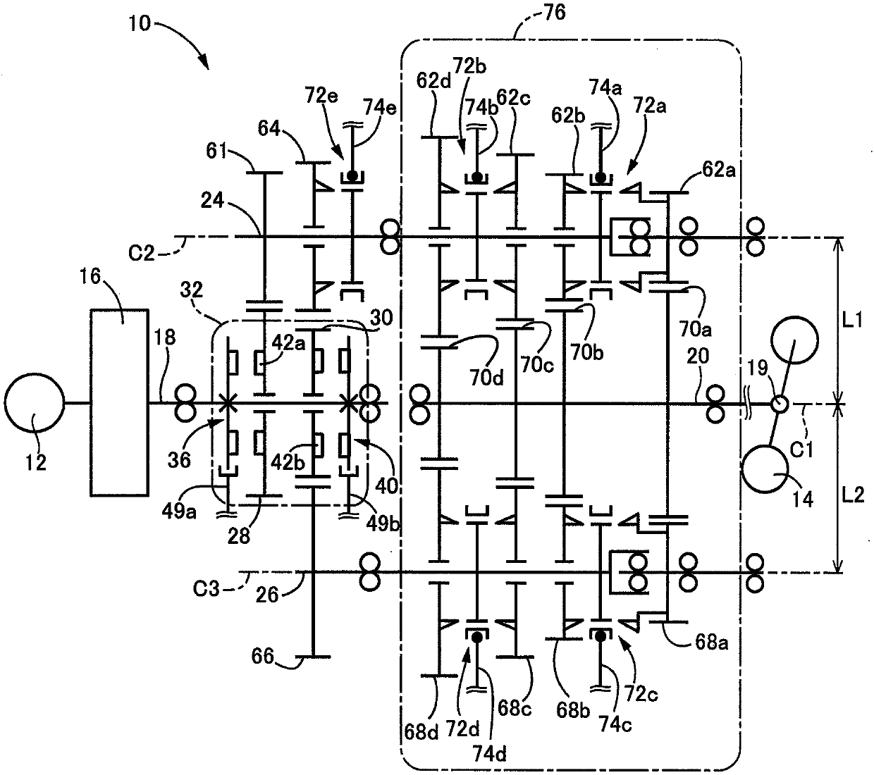
[0037] figure 1 It is a schematic diagram schematically showing the structure of a vehicle transmission 10 (hereinafter, referred to as the transmission 10 ) as an embodiment of the present invention. The transmission 10 is a multi-speed transmission provided on a power transmission path between the engine 12 and the drive wheels 14 and capable of eight forward speeds and one reverse speed.
[0038] The transmission 10 includes: an input shaft 18 that receives power from the engine 12 through a clutch 16; an output shaft 20 that is connected to the driving wheels 14 through a differential mechanism 19 and the like in a power-transmittable manner; The shaft 24 and the second shaft 26 are arranged on a power transmission path between the input shaft 18 and the output shaft 20 . The input shaft 18 and the output shaft 20 are arranged in series on the same axis C1. The first shaft 24 is arranged on an axis C2 parallel to the axis C1. The second shaft 26 is arranged on an axis C...
Embodiment 2
[0091] Figure 5 It is a schematic diagram of a vehicle transmission 100 (hereinafter, referred to as a transmission 100 ) corresponding to another embodiment of the present invention. The transmission 100 is provided on a power transmission path between the engine 12 and the driving wheels 14 . In the transmission 100 of the present embodiment, different from the transmission 10 of the foregoing embodiments, the first shaft 106 provided with the first drive gears (even-numbered drive gears) 118a to 118c constituting the even stages and the first shaft 106 provided with the first drive gears constituting the odd stages The second drive gears (odd-numbered drive gears) 122a and 122b differ in that the second shafts 108 are arranged on the common axis and are arranged at overlapping positions when viewed from the radially outer side. Hereinafter, description will focus on structures different from those of the transmission 10 of the aforementioned embodiment.
[0092] The transm...
Embodiment 3
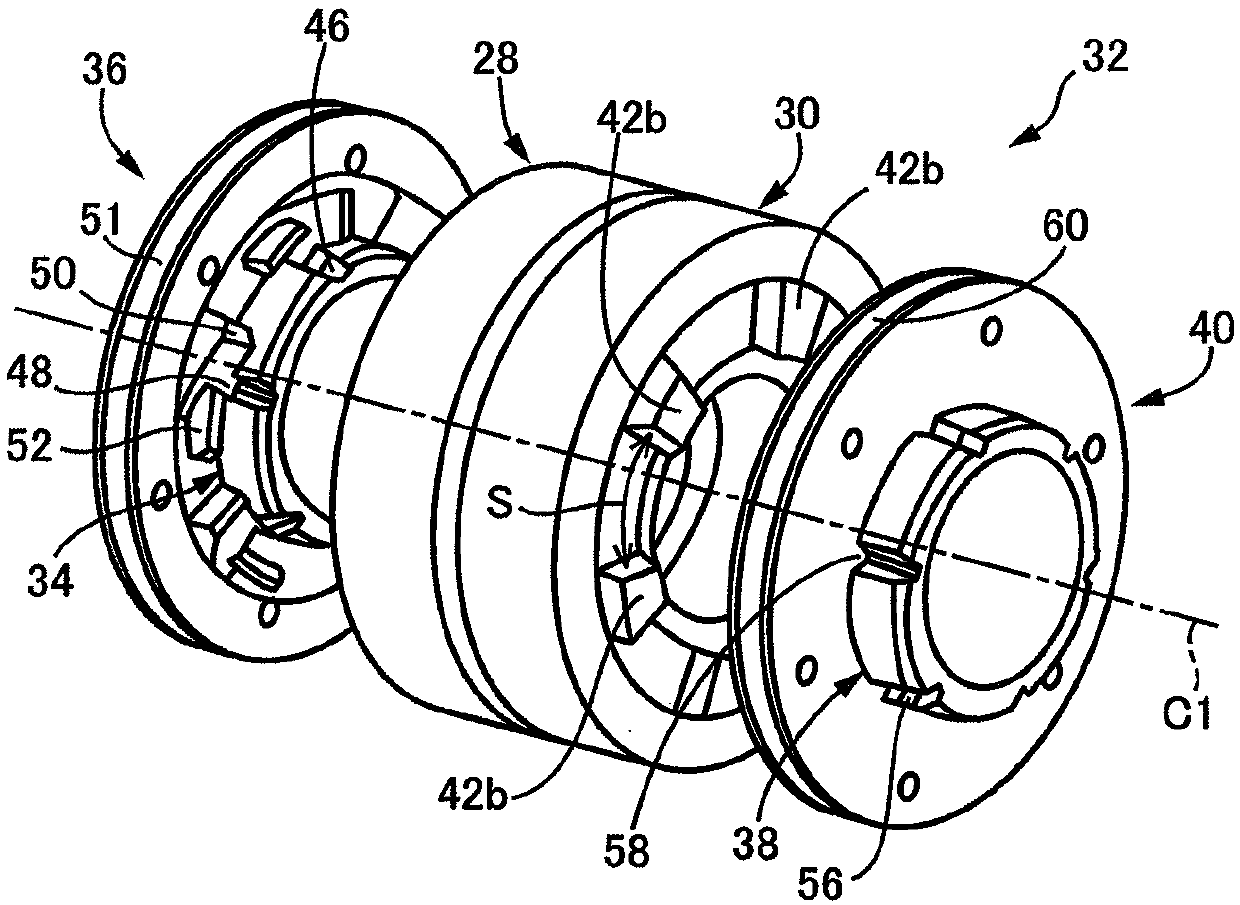
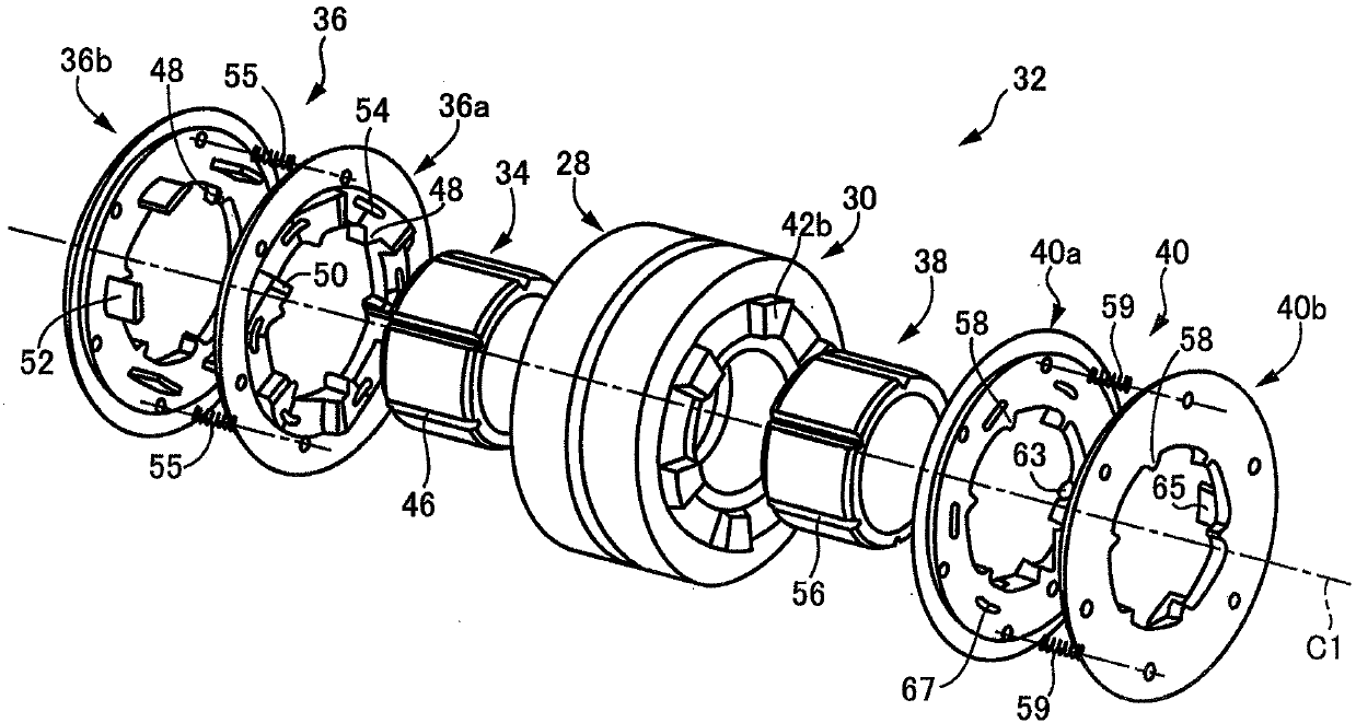
[0108] Figure 6 It is an exploded perspective view showing a dog clutch 150 corresponding to still another embodiment of the present invention. The dog clutch 150 of this embodiment is used instead of the dog clutch 32 (transmission 10) or the dog clutch 114 (transmission 100) of the above-mentioned embodiment, for example. The jaw clutch 150 of this embodiment is composed of a hub 152 and a jaw ring 154 .
[0109] The dog clutch 150 includes a hub 152 , a dog ring 154 arranged on the outer peripheral side of the hub 152 , and dogs 160 formed on the first input gear 156 and the second input gear 158 . In addition, although the cog 160 of the 2nd input gear 158 is not shown in figure, the cog 160 similar to the cog 160 of the 1st input gear 156 is formed.
[0110] The hub 152 is formed in a cylindrical shape, and is relatively non-rotatably fitted to an input shaft (not shown). In addition, a plurality of fitting grooves 162 parallel to the axis C1 are formed on the outer p...
PUM
 Abstract
Description
Claims
Application Information
 - R&D
- Intellectual Property
- Life Sciences
- Materials
- Tech Scout
- Unparalleled Data Quality
- Higher Quality Content
- 60% Fewer Hallucinations
Browse by: Latest US Patents, China's latest patents, Technical Efficacy Thesaurus, Application Domain, Technology Topic, Popular Technical Reports.
© 2025 PatSnap. All rights reserved.Legal|Privacy policy|Modern Slavery Act Transparency Statement|Sitemap|About US| Contact US: help@patsnap.com