
Distributed power generation heating and decentralized refrigeration coupling system

A distributed power generation and coupling system technology, which is applied in the field of distributed power generation heating and distributed refrigeration coupling systems, can solve the problems of increased operating costs, system inefficiency, and insufficient utilization of latent heat of condensation

Pending Publication Date: 2016-06-29
SHANGHAI HANBELL PRECISE MASCH CO LTD
View PDF6 Cites 2 Cited by
  • Summary
  • Abstract
  • Description
  • Claims
  • Application Information

AI Technical Summary

Problems solved by technology

[0007] (1) Power generation cycle of condensing steam turbine: only power generation without heat supply, so that a large amount of latent heat of condensation is not only not fully utilized, but also discharged into the environment through the evaporation of circulating water in the cooling tower, which not only consumes water resources but also causes environmental heat, Wet pollution; at the same time, the device is complicated, the investment is increased, the reliability is reduced, and the operating cost is increased, resulting in the system not being energy-saving and economical
[0008] (2) Extraction condensing steam turbine thermoelectric cycle: it not only generates electricity but also supplies heat. In summer, the condensed steam heat is still discharged to the environment through the evaporation of circulating water in the cooling tower, so it not only consumes water resources but also causes environmental heat and humidity pollution; and When steam is extracted from the middle stage of the steam turbine for heating in winter, the amount of steam extracted reduces the power generation; the cycle device is complex, with increased investment, reduced reliability, increased operating costs, no energy saving, and poor economy
However, this cycle uses heat to determine electricity, so when there is no heating load in spring, summer and autumn, the steam turbine needs to stop running, which in turn affects the gas turbine power generation cycle, resulting in gas emission

Method used


Image

  • Distributed power generation heating and decentralized refrigeration coupling system

Examples


Embodiment Construction

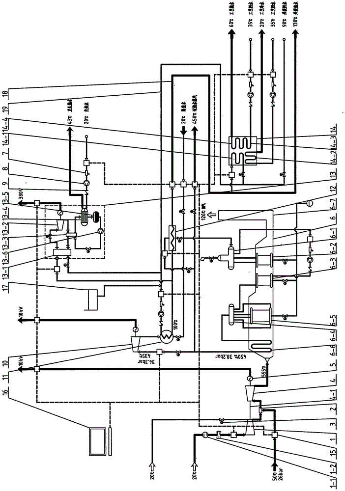
[0071] The embodiment of the distributed power generation heating and distributed refrigeration coupling system proposed by the present invention is attached figure 1 As shown, the description is as follows: it consists of a compressor 1 (with a pressure ratio of 16.8:1), a combustion chamber 2 (stainless steel with a volume of 160L), and a gas turbine 4 with a power generation capacity of 15MW to form a gas turbine;

[0072] Compressor 1, gas turbine 4, (rated power 15MW, rated voltage 10.5kV, rated current 1031A, rated frequency 50Hz, rated speed 1500r / min, power factor 0.8 synchronous) generator 5, through (stainless steel with a diameter of 75mm) The single-shaft 4-1 connection is integral and shares the base to form the first-stage cycle power generation and compressor device of the gas turbine (with a thermal efficiency of 34.8%);

[0073] (Stainless steel with a diameter of 400mm and a wall thickness of 4mm) the gas pipeline is connected to the gas inlet of the combusti...


PUM


Abstract

The invention discloses a distributed power generation heating and decentralized refrigeration coupling system which integrates energy equipment such as a gas turbine, a waste heat boiler, and a back-pressure steam turbine, as well as functional equipment such as a back-pressure heating switch loop, an organic Rankine cycle unit, a heating pipe network and an absorption unit, and balances back-pressure heating capacity and heat consumption of the functional equipment seasonally, that is, the heating pipe network supplies heat to a user end to drive a heating terminal in winter, and supplies heat to the user end to drive the absorption unit to refrigerate and then further drive an air conditioner terminal in summer. Therefore, a distributed heating and decentralized refrigeration coupling system is created for summer, a cold supply pipe network and investment thereof are eliminated, and the energy conveying cost of the heating pipe network in summer is greatly reduced.

Description

(1) Technical field [0001] The invention relates to a distributed power generation heating and distributed refrigeration coupling system in a distributed energy system. (2) Background technology [0002] In a gas-steam combined cycle power plant, electrical energy is generated in two separate power generation cycles: [0003] (1) The gas turbine generates electricity in the first stage cycle, the gas is mixed with air and combusted, and the high-pressure, high-temperature flue gas generated is sent to the gas turbine for expansion and work, which drives the impeller to rotate and drives the generator rotor to rotate to generate the first-stage power; The discharged low-pressure, high-temperature flue gas is introduced into the waste heat boiler, and the sensible heat of the flue gas is recovered to generate high-pressure, high-temperature superheated steam. [0004] (2) The second-stage cycle of the steam turbine generates electricity. The superheated steam is sent into the...

Claims


Application Information

Patent Timeline
IPC IPC(8): F02C3/04F02C6/00F02C6/18F01K23/10F01K25/10F22B1/18F25B15/00
CPCF01K23/10F01K25/10F02C3/04F02C6/00F02C6/18F22B1/1815F25B15/00Y02E20/14Y02B30/625
Inventor 侴乔力余昱暄邓壮
Owner SHANGHAI HANBELL PRECISE MASCH CO LTD
Learn More