Method and device for manufacturing an optical fiber end
- Summary
- Abstract
- Description
- Claims
- Application Information
AI Technical Summary
Benefits of technology
Problems solved by technology
Method used
Image

Examples
Embodiment Construction
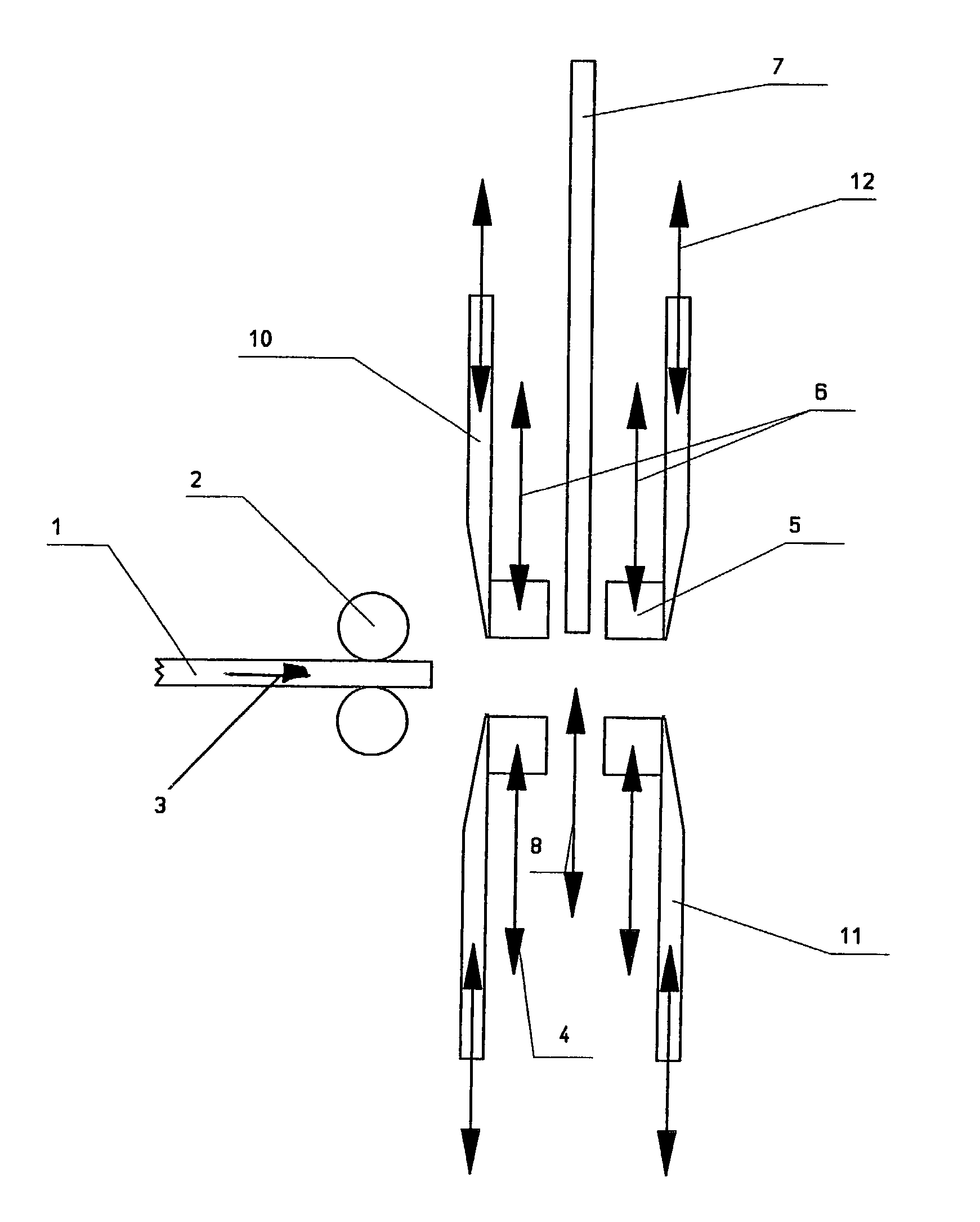
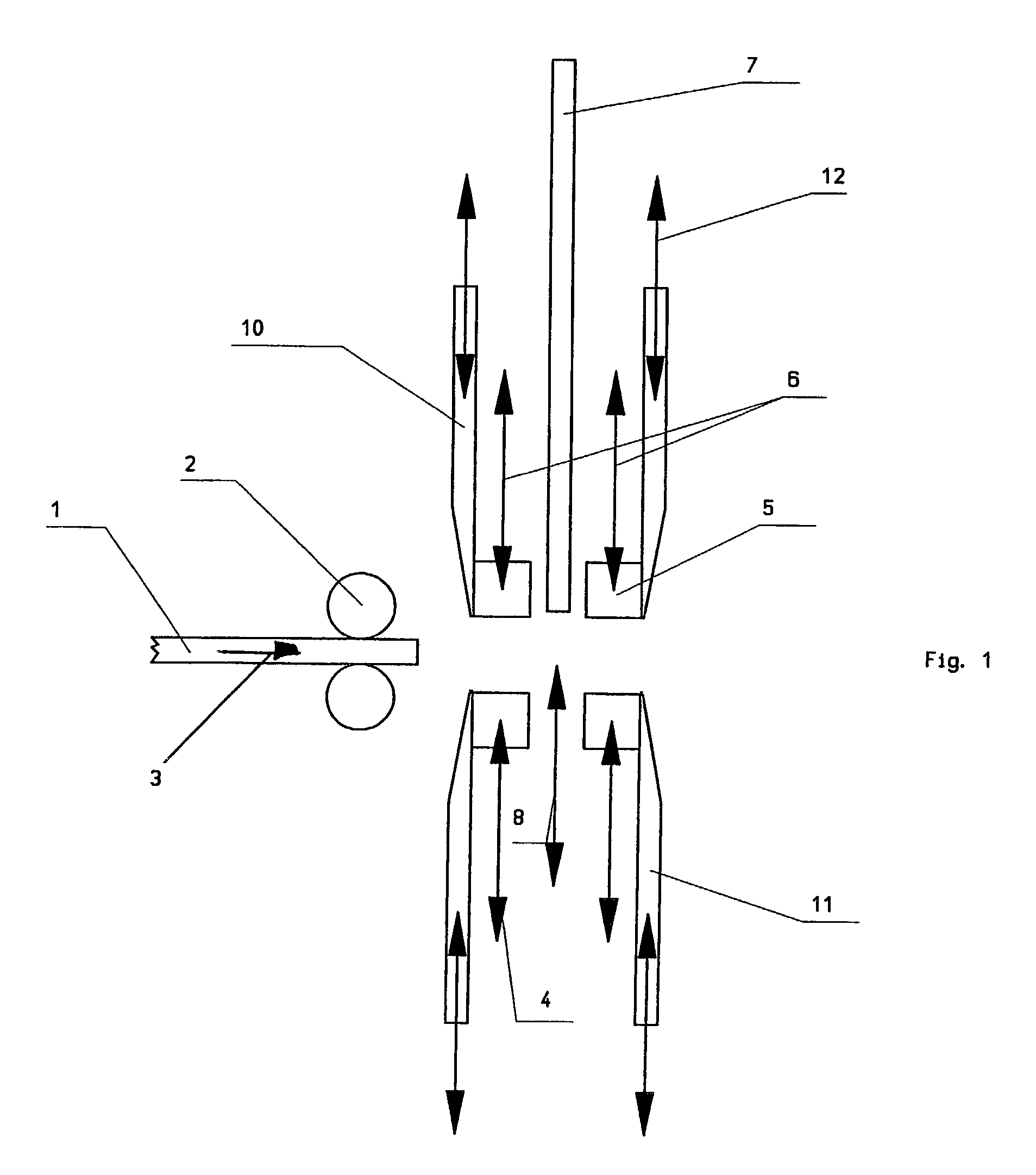
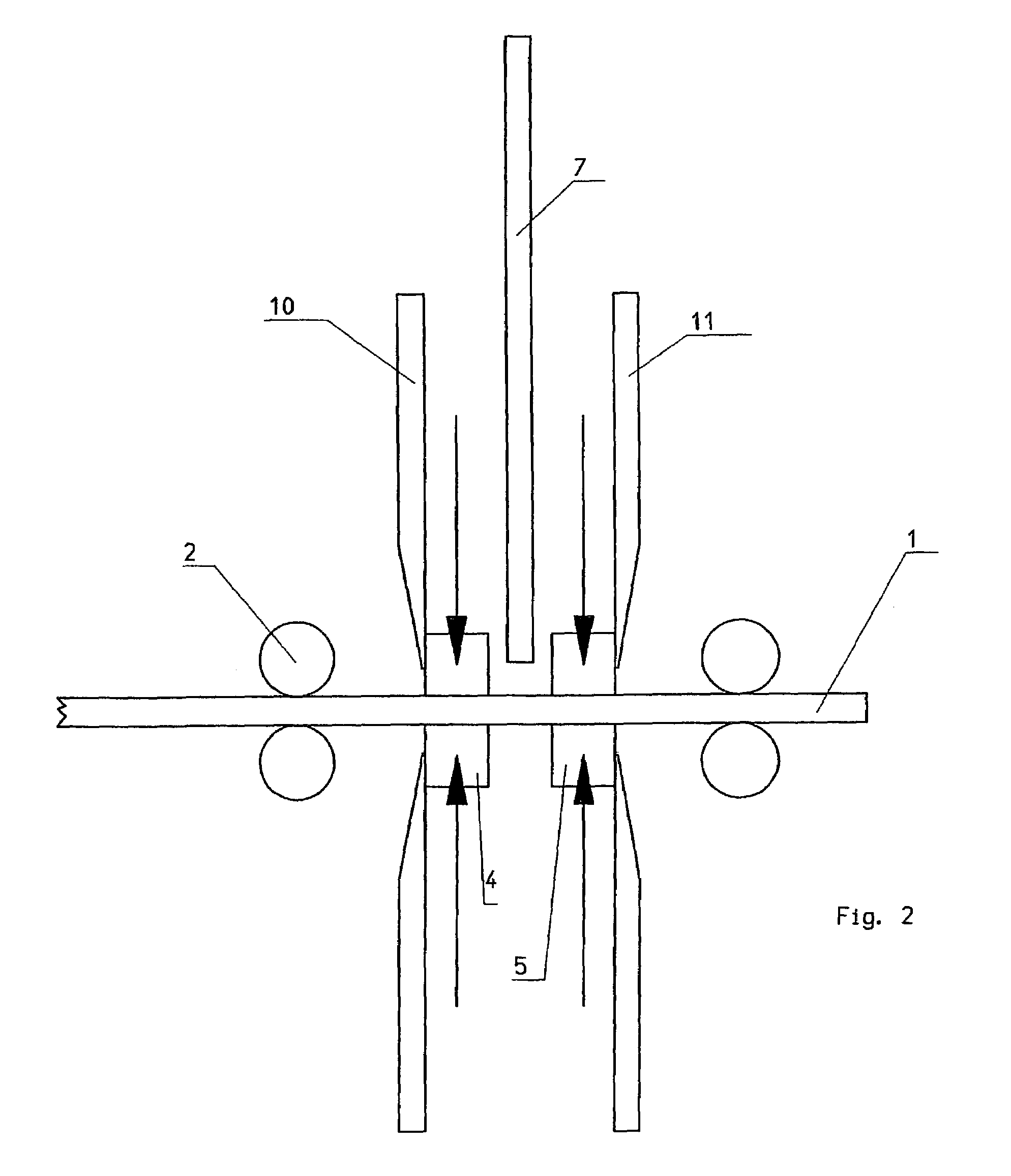
[0020]The method is schematically illustrated in FIGS. 1 to 6 on the basis of the machine parts required. The movement direction of the individual parts and / or of the optical fiber is indicated by the inset arrows. In the exemplary embodiment, the device is implemented as mirror-symmetric, so that two optical fiber ends may be manufactured simultaneously. The device is shown in its starting position in FIG. 1. Optical fiber 1 is held in combined conveyor and holding device 2 and may be moved to the right into the clamping and cutting parts of the device for the cutting through and machining procedure as indicated by arrow 3. Clamping jaws 4 and 5 are provided for clamping optical fiber 1. Clamping jaws 4 and 5 are to be moved transversely to optical fiber 1, as indicated using arrows 6. Cutting tool 7, which may be moved transversely to optical fiber 1 as shown by arrow 8, is provided between clamping jaws 4 and 5. Cutting blades 10 and 11, which may be moved back and forth in the d...
PUM
 Abstract
Description
Claims
Application Information
 - R&D
- Intellectual Property
- Life Sciences
- Materials
- Tech Scout
- Unparalleled Data Quality
- Higher Quality Content
- 60% Fewer Hallucinations
Browse by: Latest US Patents, China's latest patents, Technical Efficacy Thesaurus, Application Domain, Technology Topic, Popular Technical Reports.
© 2025 PatSnap. All rights reserved.Legal|Privacy policy|Modern Slavery Act Transparency Statement|Sitemap|About US| Contact US: help@patsnap.com