
Cutting method of multi-wire cutting machine and multi-wire cutting machine

A technology of multi-wire cutting machine and cutting method, which is applied to the parts of grinding machine tools, stone processing equipment, grinding machines, etc., can solve the problems of increasing the cost of slotting, prolong the service life, shorten the processing cycle, and improve the cutting efficiency Effect

Pending Publication Date: 2019-08-02
玉田县昌通电子有限公司
View PDF13 Cites 3 Cited by
  • Summary
  • Abstract
  • Description
  • Claims
  • Application Information

AI Technical Summary

Problems solved by technology

However, according to the processing method of the prior art, whenever the roller groove is worn and damaged, the roller must be re-grooved for reuse, which will greatly increase the cost of groove

Method used


Image

  • Cutting method of multi-wire cutting machine and multi-wire cutting machine
  • Cutting method of multi-wire cutting machine and multi-wire cutting machine
  • Cutting method of multi-wire cutting machine and multi-wire cutting machine

Examples


Embodiment Construction

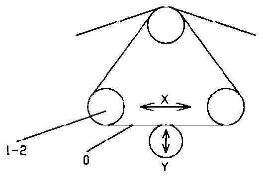
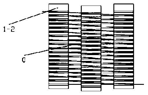
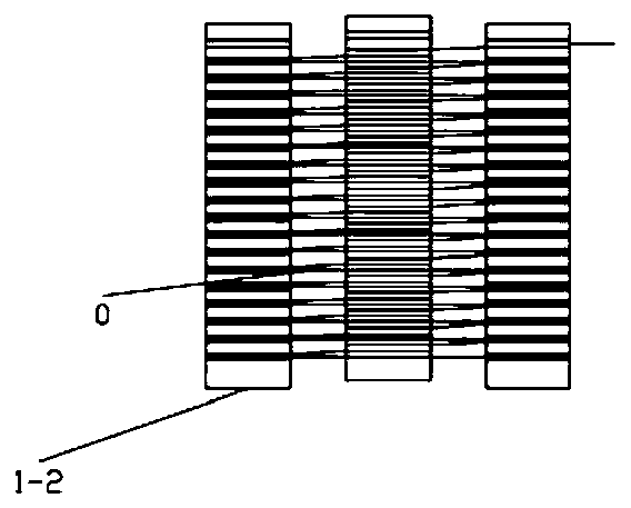
[0295] Such as Figure 4 to Figure 36 As shown, this embodiment provides a cutting method for a multi-wire cutting machine, only winding a circle of steel wire 0 on the roller 1-2; or, winding multiple turns of steel wire 0 on the roller 1-2, two adjacent The distance between the hoop steel wires 0 is greater than or equal to twice the minimum distance between the two wire grooves 1-2-1 adjacent to the roller 1-2 and less than or equal to the distance between the wire grooves 1-2-1 at both ends of the roller 1-2 When cutting, after cutting the previous knife and before the next knife to be cut, first make the cutting material withdraw from the steel wire 0, and then move the cutting material along the direction of the length of roller 1-2 for a distance, the distance Equal to the thickness of the slice.

[0296] In this embodiment, only one circle of steel wire is wound on the roller; or, multiple circles of steel wire are wound on the roller, and the distance between two adj...


PUM

PropertyMeasurementUnit
thicknessaaaaaaaaaa
thicknessaaaaaaaaaa

Abstract

The invention discloses a cutting method of a multi-wire cutting machine and the multi-wire cutting machine. The method comprises the following steps that a circle of steel wire is wound around a roller; or a plurality of circles of steel wires are wound around the roller, and the distance between every two adjacent circles of steel wires is larger than or equal to twice of the minimum distance between the two adjacent line grooves of the roller and is smaller than or equal to the distance between the line grooves at the two ends of the roller; and when the cutting is carried out, the cuttingmaterial is taken out of the steel wire after last cutting is done and before the next cutting is carried out, and then the cutting material is moved a certain distance along the length direction of the roller, and the distance is equal to the thickness of the slice. The multi-wire cutting machine comprises a cutting part and a feeding part, the cutting part comprises an X-direction reciprocatinglinear motion mechanism, the feeding part comprises a material plate, a Y-direction reciprocating linear motion mechanism and a Z-direction reciprocating linear motion mechanism, the X direction, theY direction and the Z direction are perpendicular to each other. According to the cutting method of the multi-wire cutting machine and the multi-wire cutting machine, the cutting slices with any thickness can be cut by using the roller with the same groove distance, and the requirement of small-batch multi-variety processing is met.

Description

technical field [0001] The invention relates to a cutting method of a cutting machine and the cutting machine thereof, in particular to a cutting method of a multi-wire cutting machine and the multi-wire cutting machine. Background technique [0002] Multi-wire cutting machine is a cutting machine that winds steel wire on multiple rollers to form multiple parallel steel wires. The multi-parallel steel wires of the multi-wire cutting machine are driven by multiple rollers, and move backwards on the cutting material at the same time, and cut the hard and brittle materials into multiple sliced ​​products with a thickness corresponding to the groove distance of the rollers through friction cutting. [0003] Such as Figure 1 to Figure 3 As shown, the cutting method of the multi-wire cutting machine in the prior art is usually to open rollers with different groove pitches for slices of different thicknesses. However, the equipment and process used for roller grooving require a l...

Claims


Application Information

Patent Timeline
Patent Type & Authority Applications(China)
IPC IPC(8): B24B27/00B24B27/06B24B41/00B24B41/04B24B41/06B24B47/12B24B47/20B24B47/22B24B51/00B28D1/22B28D7/00B28D7/04
CPCB24B27/0633B24B41/04B24B41/00B24B51/00B24B47/12B24B41/005B24B47/22B24B27/0069B24B47/20B24B41/06B28D1/22B28D7/005B28D7/04B28D7/00Y02P70/10
Inventor 章博
Owner 玉田县昌通电子有限公司
Learn More