Method for analyzing vibration characteristics of bearing retainer based on finite elements
A technology of bearing cage and analysis method, applied in the field of vibration characteristic analysis of bearing cage based on finite element, can solve the stress of cage vibration circumferential direction, the fracture of aero-engine bearing cage, and the automatic analysis program without vibration characteristics And other issues
- Summary
- Abstract
- Description
- Claims
- Application Information
AI Technical Summary
Problems solved by technology
Method used
Image
Examples
specific Embodiment approach 1
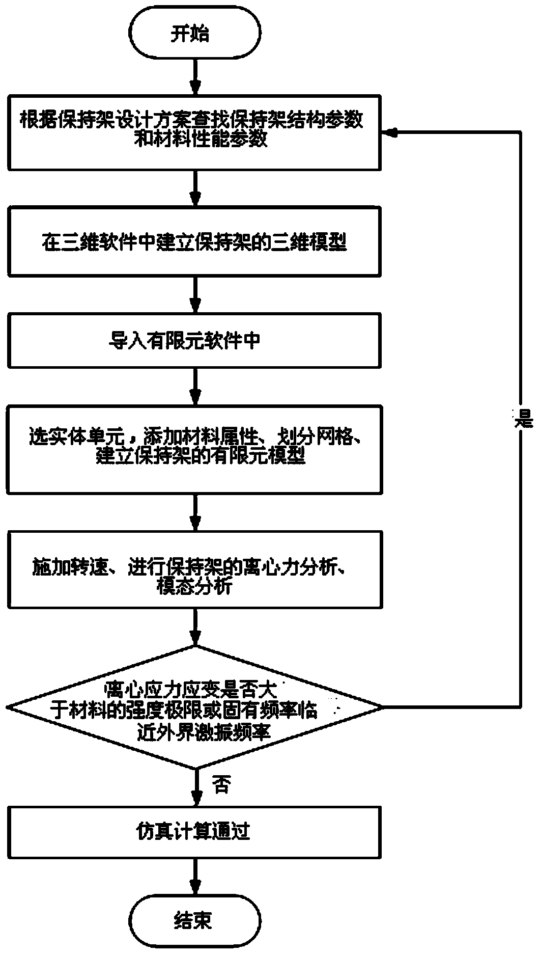
[0021] Specific Embodiment 1: A method for analyzing the vibration characteristics of a bearing cage based on finite elements in this embodiment is specifically prepared according to the following steps:
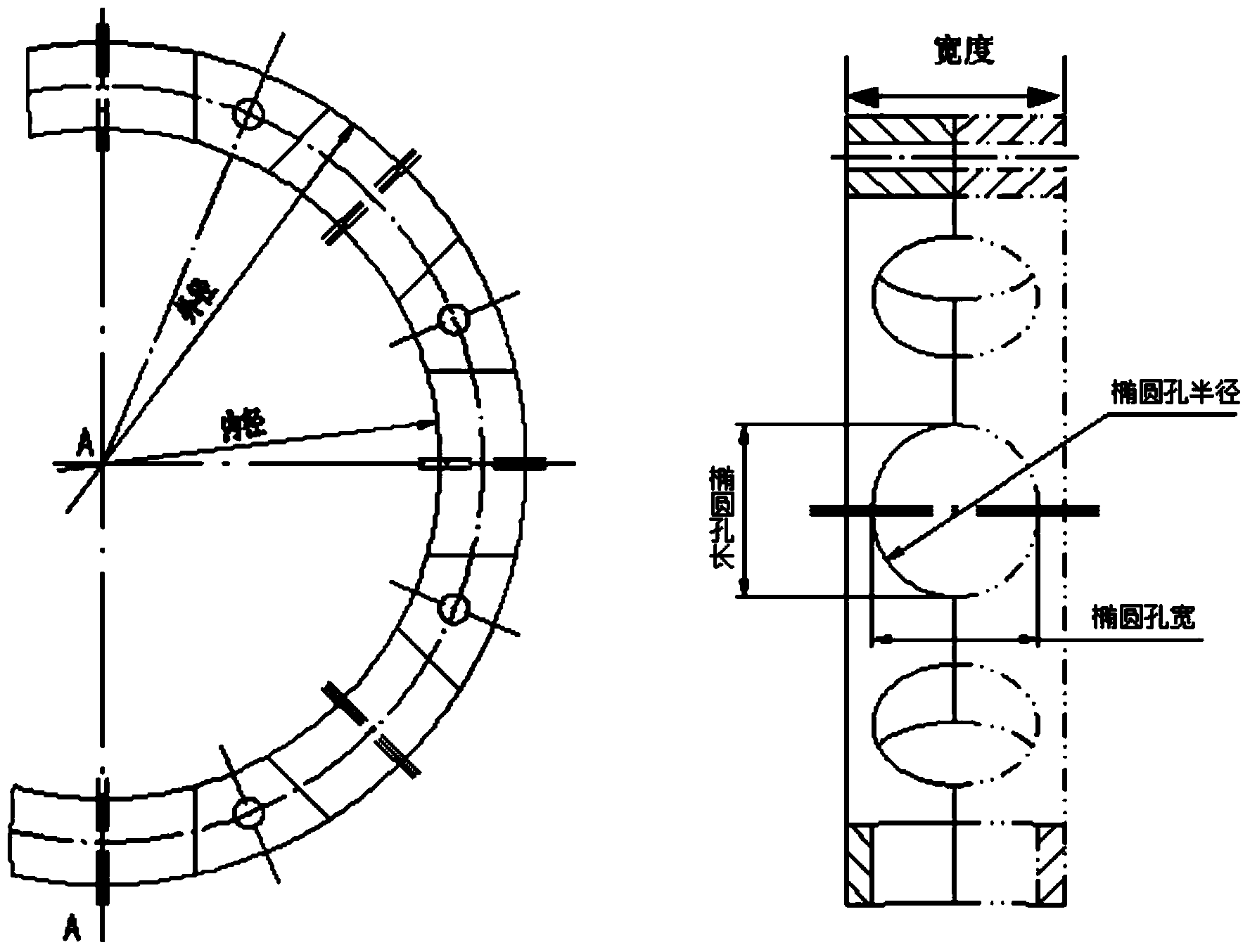
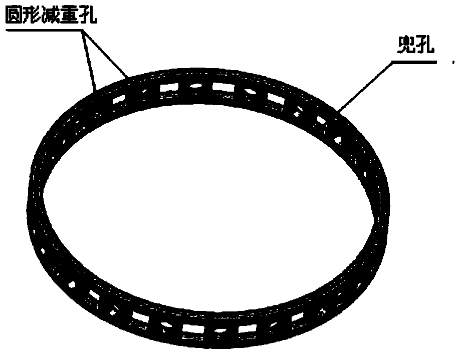
[0022] Step 1. Use 3D software to create a 3D model of the bearing cage based on the structural parameter information of the bearing cage. Figure 3(a) ~ Figure 3(b) shown, and use the format recognizable by the finite element software to store it in the working directory set by the finite element software, that is, the location specified by the computer; among them, the design of the bearing cage is a part of the bearing design, and the bearing structure is based on the used speed, The structural parameters of the cage include inner diameter, outer diameter, width, pocket diameter, number of pockets and number of lightening holes determined by the load, installation position and service temperature; the structural parameters and material performance parameters directly affec...
specific Embodiment approach 2
[0029] Specific embodiment two: the difference between this embodiment and specific embodiment one is that in step one, using three-dimensional software to create a three-dimensional model of the bearing cage according to the structural parameter information of the bearing cage is to use CAD three-dimensional design software (Solidwork, Ug, Catia , Inventer, etc.) established. Other steps and parameters are the same as those in Embodiment 1.
specific Embodiment approach 3
[0030] Embodiment 3: The difference between this embodiment and Embodiment 1 or 2 is that the finite element software in step 1 is a calculation method commonly used in engineering at present. Engineering technical problems; theoretically speaking, that is, the process of idealizing a continuum with infinite degrees of freedom into a unit body assembly with only a limited number of degrees of freedom, and using structural analysis methods to find its numerical solution; the current finite element software includes ANSYS , ABQUES, and PERMAS. The APDL language in the ANSYS software is used here to import the three-dimensional graphics into the finite element software through programming, set the material properties of the bearing cage, select the solid unit, and divide the grid. Using the APDL language in the ANSYS software Command streams written in languages such as Figure 4 As shown, the finite element mesh model divided by solid elements is as follows Figure 5 shown. ...
PUM
 Abstract
Description
Claims
Application Information
 - R&D
- Intellectual Property
- Life Sciences
- Materials
- Tech Scout
- Unparalleled Data Quality
- Higher Quality Content
- 60% Fewer Hallucinations
Browse by: Latest US Patents, China's latest patents, Technical Efficacy Thesaurus, Application Domain, Technology Topic, Popular Technical Reports.
© 2025 PatSnap. All rights reserved.Legal|Privacy policy|Modern Slavery Act Transparency Statement|Sitemap|About US| Contact US: help@patsnap.com


