Eureka AIR delivers breakthrough ideas for toughest innovation challenges, trusted by R&D personnel around the world.

Support Structure for a Light Source, a Backlight Unit for a Display Device Having the Support Structure, and a Display Device

a technology of support structure and light source, which is applied in the direction of lighting support devices, instruments, lighting and heating apparatus, etc., can solve the problem of contact noise caused by the end of the light source with the other members, and achieve the effect of preventing contact nois

Inactive Publication Date: 2008-05-01
SHARP KK
View PDF6 Cites 20 Cited by
  • Summary
  • Abstract
  • Description
  • Claims
  • Application Information

AI Technical Summary

Benefits of technology

[0011]In order to overcome the problems described above, preferred embodiments of the present invention provide a support structure for a light source which is capable of preventing a contact noise caused by vibrations of cold cathode tubes, and a backlight unit having such a support structure.
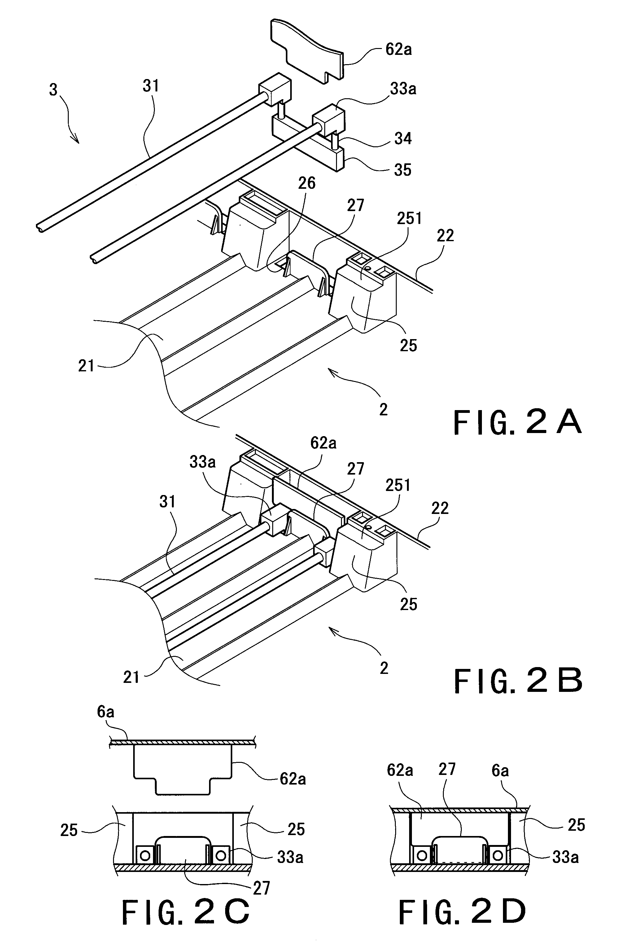
[0015]In addition, since the end of the light source is secured while put between the chassis and the frame, only by placing the light source on the chassis and attaching the frame thereto, the light source is secured. Thus, the necessity of previously securing the light source to the chassis as conventional is eliminated, simplifying an operation of installing the light source.
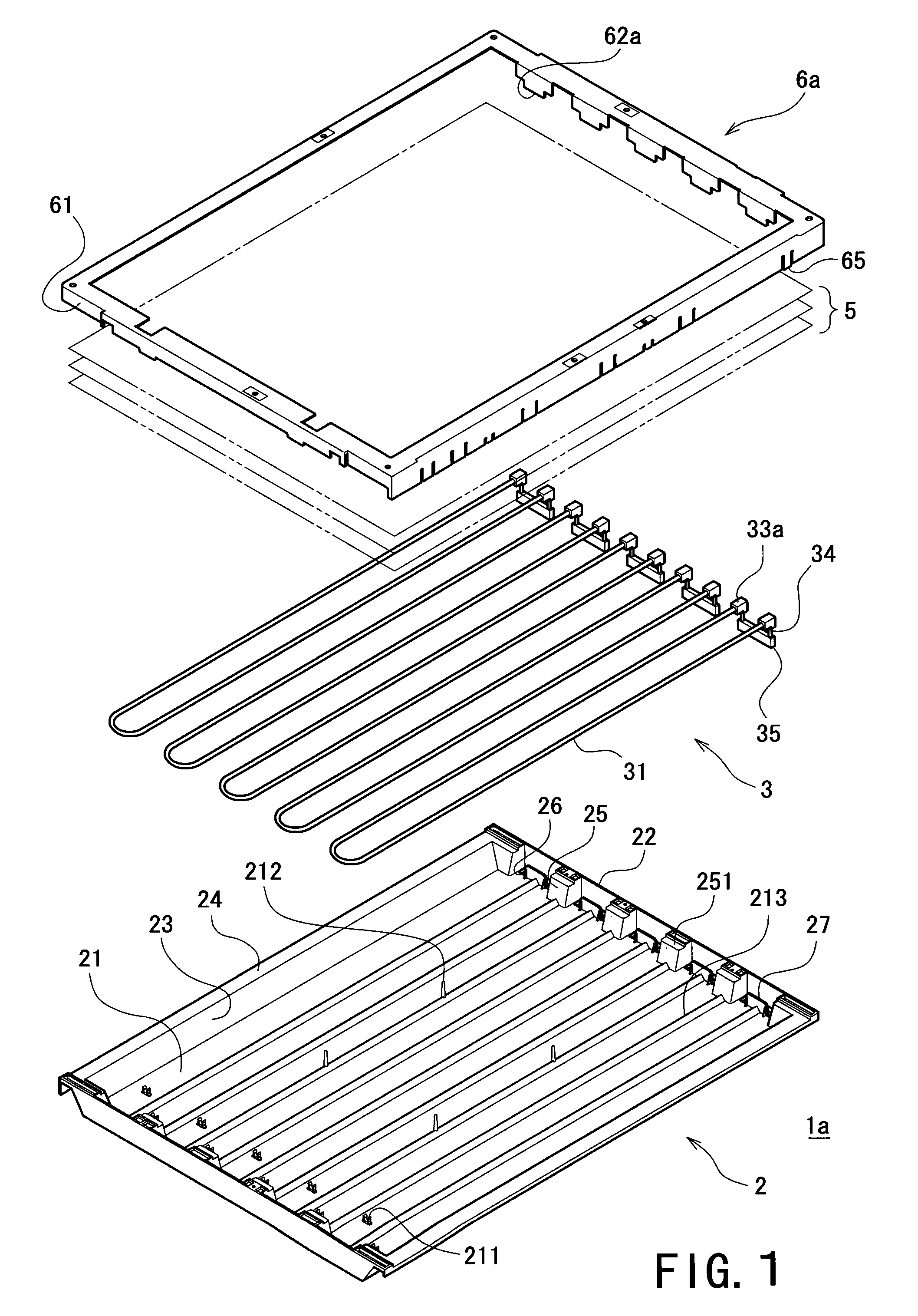
[0016]By applying the configuration in which the notch which is capable of fitting to the end of the light source is formed in the frame and the end of the light source is fit to the notch, the end of the light source is more firmly secured, ensuring prevention of the vibrations.
[0017]In a case where a product incorporating the backlight unit having the above-described configurations includes a loudspeaker system such as a speaker, even if vibrations from the speaker propagate to the light source during the use of the product, resonance of the light source can be prevented, so that a contact noise which could be perceived as an unusual noise by the user during use can be prevented.

Problems solved by technology

Therefore, a contact noise caused by the contact of the end of the light source with the other members is not made even if the light source vibrates.

Method used


Image

  • Support Structure for a Light Source, a Backlight Unit for a Display Device Having the Support Structure, and a Display Device
  • Support Structure for a Light Source, a Backlight Unit for a Display Device Having the Support Structure, and a Display Device
  • Support Structure for a Light Source, a Backlight Unit for a Display Device Having the Support Structure, and a Display Device

Examples


Embodiment Construction

[0025]A detailed description of preferred embodiments of the present invention will now be given with reference to the accompanying drawings.

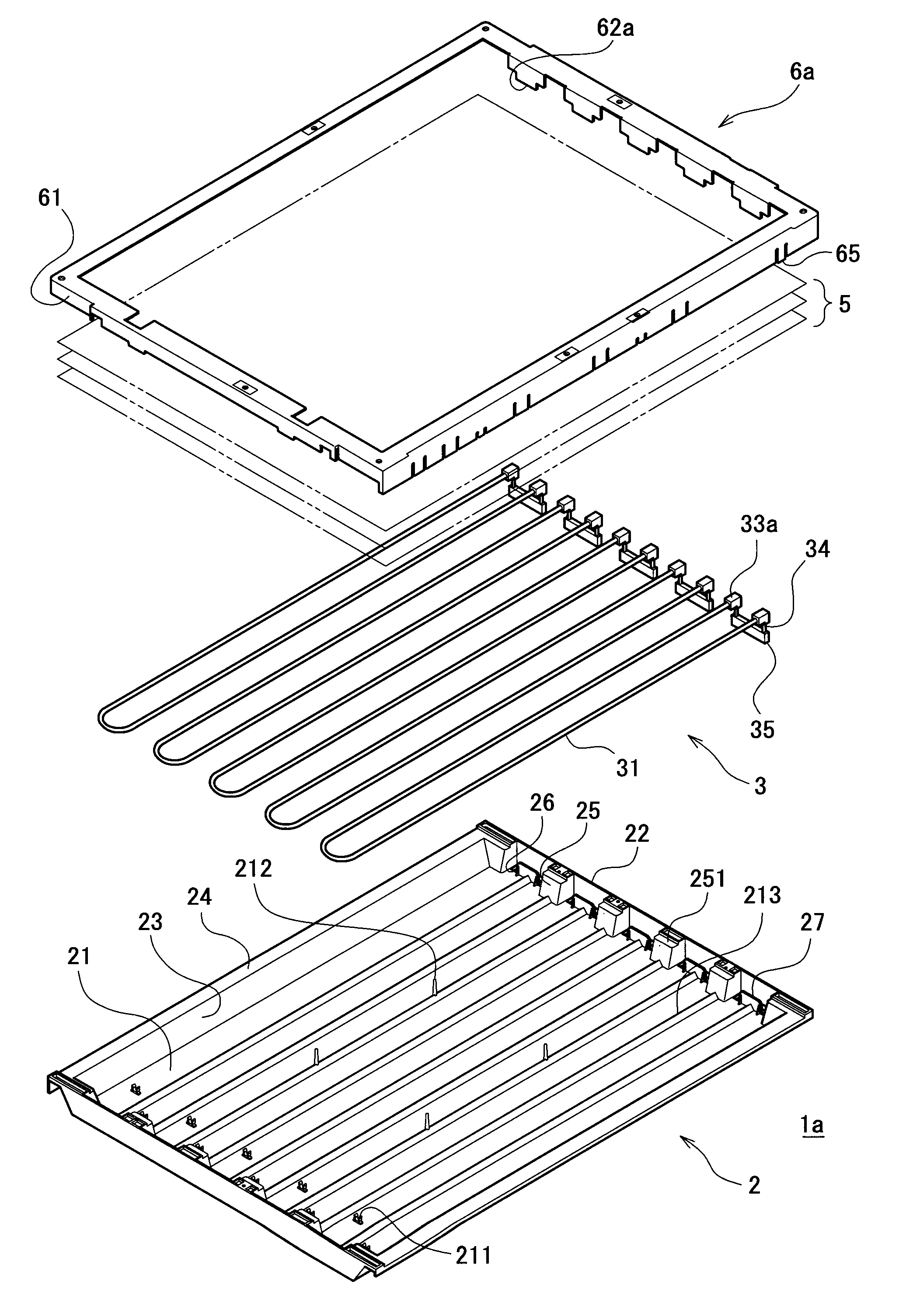
[0026]FIG. 1 is a view showing a first preferred embodiment of the backlight unit having the support structure for the light source according to the present invention, to be specific, an exploded perspective view schematically illustrating a structure for assembling the backlight unit having the support structure for the light source according to the present invention. In FIG. 1, the backlight unit is illustrated so that its front surface faces toward the top of FIG. 1, and its back surface faces toward the bottom of FIG. 1, based on which the following descriptions will be given.

[0027]First, a short summary of a configuration of the backlight unit is given with reference to FIG. 1. The backlight unit 1a includes a backlight unit 2 as a chassis of the backlight unit 1a, a plurality of cold cathode tubes 3 as light sources (FIG. 1 shows a config...


PUM


Abstract

A support structure for a light source prevents the occurrence of a contact noise caused by contact of the light source with elements disposed around it due to vibrations. In the support structure, at the front of a backlight unit, cold cathode tubes as light sources and optical sheets for controlling the properties of light emitted from the cold cathode tubes are placed, and a frame substantially in the shape of a square with an opening is attached thereto from the front, so that rubber holders attached to the ends of the cold cathode tubes and the edges of the optical sheets are secured while disposed between the backlight unit and the frame.

Description

BACKGROUND OF THE INVENTION[0001]1. Field of the Invention[0002]The present invention relates to a support structure for a light source and a backlight unit for a display device having the support structure, and specifically relates to a support structure for a light source preferably used in a liquid crystal display device including a translucent liquid crystal display panel and a backlight unit for a display device having the support structure.[0003]2. Description of the Related Art[0004]A liquid crystal display device including a translucent liquid crystal display panel or the like, which is cited as an example of a flat-screen display device, generally has a configuration in which a backlight unit is placed at the back of the liquid crystal display panel. The backlight unit is a device having an internal light source, which controls the properties of light emitted from the light source and projects the light toward the back surface of the liquid crystal display panel. The projec...

Claims


Application Information

Patent Timeline
Patent Type & Authority Applications(United States)
IPC IPC(8): F21V21/00F21Y103/37
CPCF21V15/04F21V19/009G02F1/133608G02F1/133604F21V19/0095
Inventor OGURA, TAKESHINAKAMICHI, KAZUKIMURAKAMI, YOSHIHIROOHNISHI, TAKUYAHARA, TAKAFUMI
Owner SHARP KK
Why Eureka
Eureka Blog
Learn More