
Intermittent rib inner cooling structure used for gas turbine blade

A technology of turbine blades and gas turbines, which is applied in the direction of blade support components, mechanical equipment, engine components, etc., can solve the problem of air volume reduction, etc., and achieve the effects of reducing pressure loss, enhancing heat transfer, and enhancing heat transfer

Inactive Publication Date: 2019-07-23
HARBIN ENG UNIV
View PDF5 Cites 12 Cited by
  • Summary
  • Abstract
  • Description
  • Claims
  • Application Information

AI Technical Summary

Problems solved by technology

The reduction of air volume will bring challenges to the cooling structure design of the turbine

Method used


Image

  • Intermittent rib inner cooling structure used for gas turbine blade
  • Intermittent rib inner cooling structure used for gas turbine blade
  • Intermittent rib inner cooling structure used for gas turbine blade

Examples


Embodiment Construction

[0016] The present invention is described in more detail below in conjunction with accompanying drawing example:

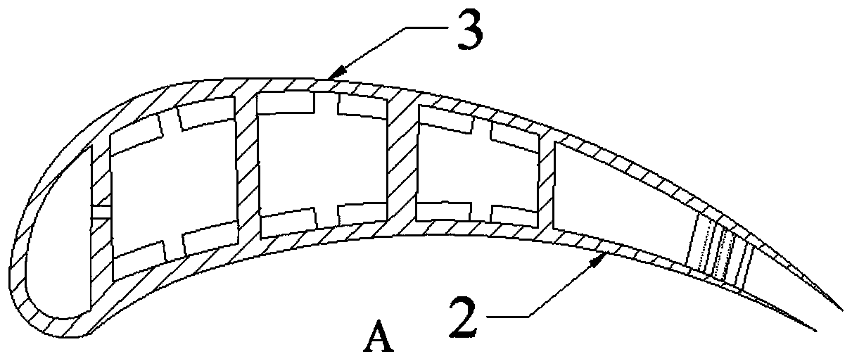
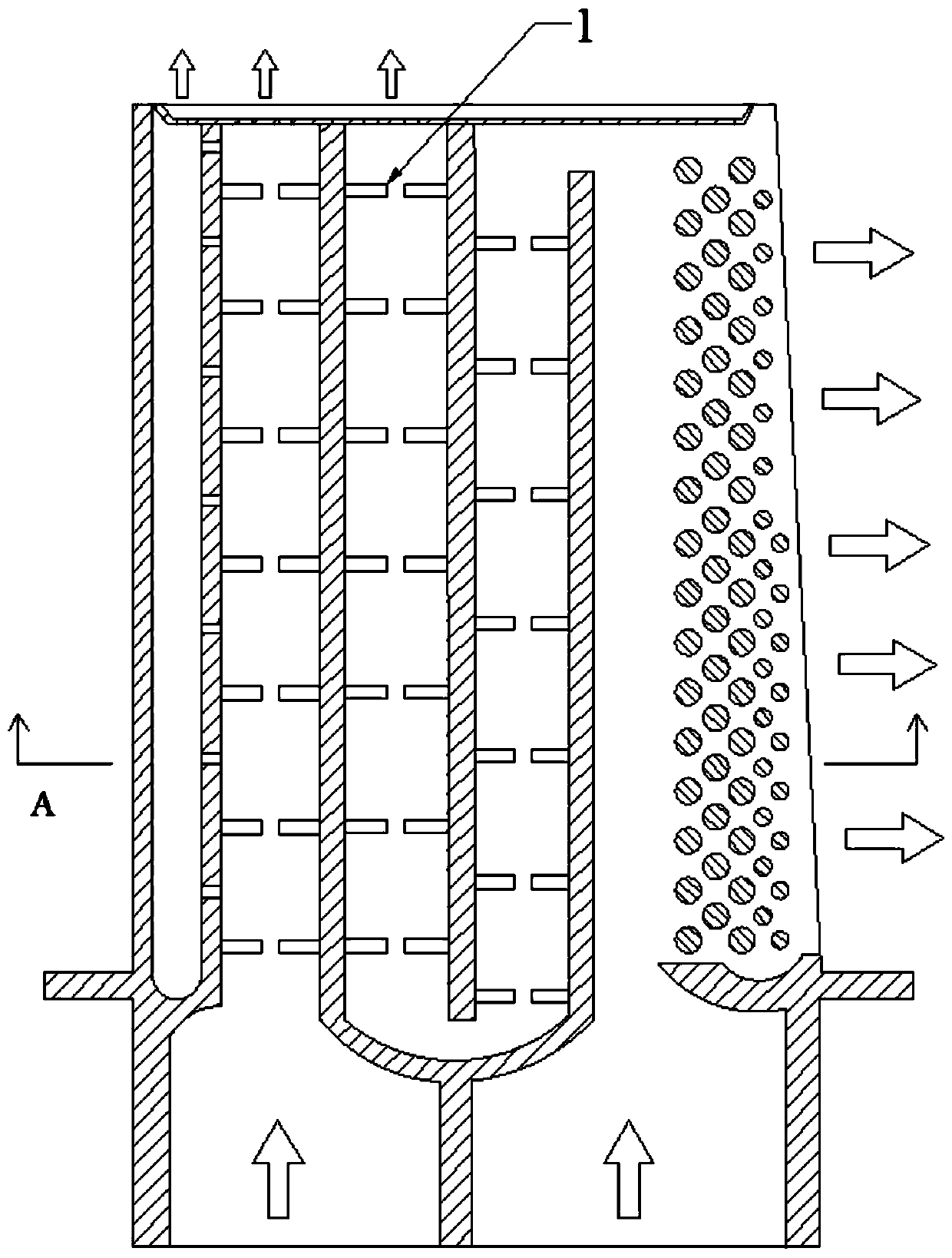
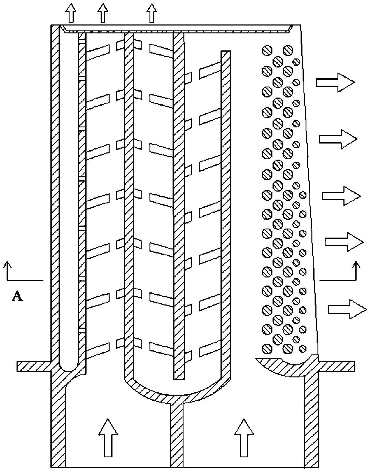
[0017] combine Figure 1-3 , the present invention is an internal cooling structure of discontinuous ribs for gas turbine blades, comprising an upper wall 3 , a lower wall 2 and discontinuous ribs 1 . The upper wall 1 is the suction surface of the blade, and the lower wall 2 is the pressure surface of the blade. The discontinuous rib 1 is located in the serpentine cooling channel of the turbine blade, and two rows of discontinuous ribs 1 are respectively located inside the upper wall 3 and the lower wall 2 of the blade. The discontinuous rib 1 is a straight rib, which can be perpendicular to the wall of the serpentine cooling channel, or can be inclined 30° to 60° relative to it. The interrupted rib 1 is equivalent to opening a fracture in a traditional complete rib. The width of the fracture is equal to the height of the rib 1, and the direction of the opening ...


PUM


Abstract

The invention aims at providing an intermittent rib inner cooling structure used for a gas turbine blade. The structure comprises an upper wall and a lower wall. A blade main body structure is definedby the upper wall and the lower wall. A left side wall and a right side wall are arranged in the blade main body structure. The left side wall is located on one side of the front edge of the blade main body structure. The left side wall and the blade main body structure form a blade front edge impact cooling channel. The right side wall is located in the middle of the blade main body structure. Left side wall air holes are formed in the left side wall. A U-shaped fork wall is arranged in the blade main body structure. The lower end portion of the U-shaped fork wall partitions the blade root into a left air inlet portion and a right air inlet portion. The right side wall is located in the middle of the U-shaped fork wall. Air outlets are formed in the tail edge portion of the blade main body structure. Intermittent ribs are arranged on the inner side of the upper wall and the inner side of the lower wall correspondingly. Fractures of the ribs have strong turbulence on airflow, the extent of separating produced by flowing of gas is increased, accordingly, the boundary layer damage extent is increased, the fluid turbulence degree is greatly increased, and heat exchanging is greatly improved.

Description

technical field [0001] The invention relates to a gas turbine blade, in particular to a blade cooling structure. Background technique [0002] Gas turbines have the characteristics of light weight, small size, high power per unit, fast start-up, less pollution, high thermal efficiency, and good economy. It can be seen from the simple cycle mode of the gas turbine that the specific power and performance can be improved by increasing the initial temperature of the gas. The position where the turbine blades are located has high temperature, complex stress, and harsh working environment, so whether the turbine blades can work safely and reliably is very important to the operation of the engine. Various performance indicators of the blades have become an important indicator to measure the development of the engine, especially the ability of the turbine blades to withstand high temperatures. In short, the development level of turbine blades has become an important symbol to meas...

Claims


Application Information

Patent Timeline
Patent Type & Authority Applications(China)
IPC IPC(8): F01D5/18
CPCF01D5/187F05D2260/201F05D2260/2212F05D2260/22141
Inventor 栾一刚符昊殷越孙涛王忠义王松万雷
Owner HARBIN ENG UNIV
Learn More