Porous medium turbulent flow jet cooling device

A technology of jet cooling and porous media, used in cooling/ventilation/heating retrofits, electrical components, electrical equipment structural parts, etc.

Pending Publication Date: 2021-05-11
CRRC DALIAN INST CO LTD
View PDF9 Cites 2 Cited by
  • Summary
  • Abstract
  • Description
  • Claims
  • Application Information

AI Technical Summary

Problems solved by technology

[0003] The invention provides a porous medium turbulent jet cooling device to solve the heat dissipation problem of high heat flux density

Method used


Image

  • Porous medium turbulent flow jet cooling device
  • Porous medium turbulent flow jet cooling device
  • Porous medium turbulent flow jet cooling device

Examples


Embodiment Construction

[0022] In order to make the purpose, technical solutions and advantages of the embodiments of the present invention clearer, the technical solutions in the embodiments of the present invention will be clearly and completely described below in conjunction with the drawings in the embodiments of the present invention. Obviously, the described embodiments It is a part of embodiments of the present invention, but not all embodiments. Based on the embodiments of the present invention, all other embodiments obtained by persons of ordinary skill in the art without creative efforts fall within the protection scope of the present invention.

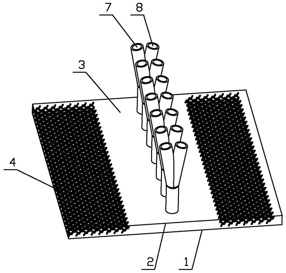
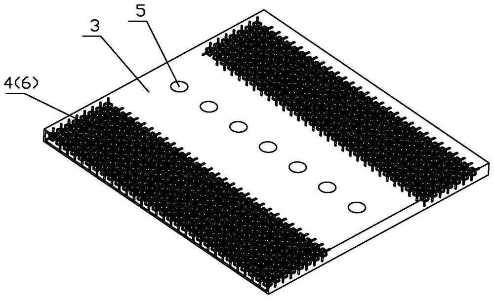
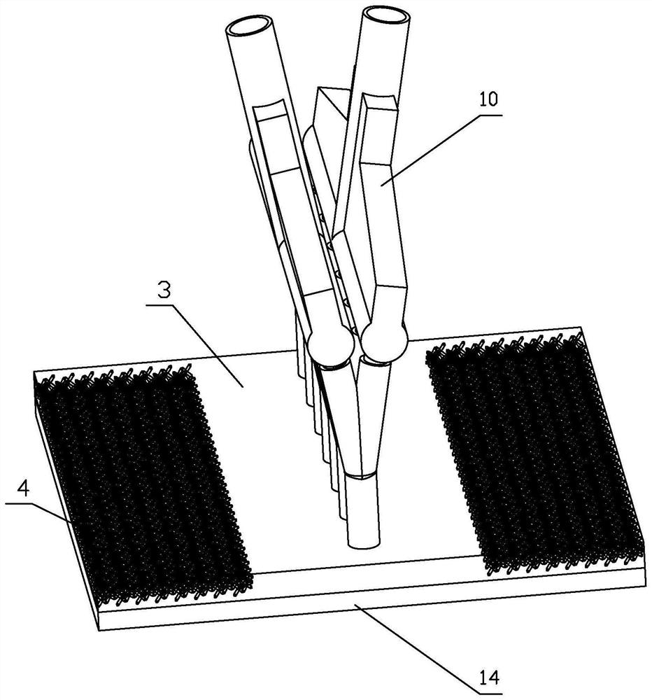
[0023] Such as Figure 1-3 As shown, a porous medium turbulent jet flow cooling device is characterized in that it includes: a first cold plate 1 and a second cold plate 2, the first cold plate 1 is close to the heating element 14, the first cold plate There is a jet cavity 3 between the plate 1 and the second cold plate 2, the second cold plate ...


PUM


Abstract

The invention provides a porous medium turbulent flow jet flow cooling device which comprises a first cold plate and a second cold plate. The first cold plate is tightly attached to a heating element, a jet flow cavity is formed between the first cold plate and the second cold plate, the second cold plate is provided with jet flow holes, jet flow enters the jet flow cavity through the jet flow holes and impacts the first cold plate. The impacted surface of the first cold plate is a smooth surface; a turbulent flow cavity is further formed between the first cold plate and the second cold plate, the turbulent flow cavity is communicated with the jet flow cavity, and a porous medium is arranged in the turbulent flow cavity. The fluid passes through the jet flow inlet and impacts the inner surface of the first cold plate, the flow path is short, and a flow boundary layer on the impacted surface is thin, so that the area which is directly impacted generates a very strong heat exchange effect. And after the heat exchanger passes through the turbulent flow porous medium, the porous medium destroys a flow boundary layer formed in the flow channel and increases turbulent flow in the flow, so that the heat exchange effect is further enhanced.

Description

technical field [0001] The invention relates to the field of heat dissipation devices, in particular to a porous medium turbulent flow jet cooling device. Background technique [0002] With the advancement of microelectronics technology, the development of miniaturization and miniaturization of electronic devices has been promoted. The reduction in the size of electronic devices has also greatly increased the heat flux of electronic devices, which puts forward more stringent requirements for the heat dissipation of microelectronic devices. Therefore, effectively solving the heat dissipation problem of high heat flux has become a key technology that must be solved in the development of electronic equipment. Contents of the invention [0003] The invention provides a porous medium turbulent jet flow cooling device to solve the heat dissipation problem of high heat flux density. [0004] A porous medium turbulent jet cooling device, comprising: a first cold plate and a secon...

Claims


Application Information

Patent Timeline
Patent Type & Authority Applications(China)
IPC IPC(8): H05K7/20
CPCH05K7/20272
Inventor 张延蕾刘俊杰孔丽君阎凯
Owner CRRC DALIAN INST CO LTD
Why Eureka
Try Eureka