Stylized transfer device based on bionic structure

A bionic and transfer printing technology, which is applied in the manufacture of electrical components, circuits, semiconductors/solid-state devices, etc., can solve problems such as thermal expansion, uncontrollable speed, and high failure rate, and achieve low operating skill requirements, efficient pick-up and put down, and realization transfer effect

Active Publication Date: 2020-01-10
TSINGHUA UNIV
View PDF2 Cites 0 Cited by
  • Summary
  • Abstract
  • Description
  • Claims
  • Application Information

AI Technical Summary

Problems solved by technology

For example, by adjusting the transfer speed to achieve the effect of "fast tearing and slow printing", that is, the peeling is completed at a higher speed and the printing is realized at a lower speed, but the failure rate is high due to the difficulty in controlling the speed
Later, some scholars proposed to prepare microstructures on the surface of the transfer stamp, such as preparing micro-protrusions at the four corners of the stamp, so as to change the contact area between the stamp and the target, and realize the peeling and printing steps in transfer printing. However, the microstructure may Destroys the target and is difficult to align with the target
Some scholars proposed to prepare a series of micro-column structures on the surface of the stamp, and realize the control of interface adhesion by changing the size and distance between the micro-column structures, but there is also the problem of difficulty in aligning the micro-column structures with the target.
Later, some scholars proposed to change the characteristics of the shape memory polymer by local heating of the laser to realize the transfer step, but the thermal effect of the laser is easy to cause thermal expansion.
[0004] Transfer printing technology plays a bridge role between traditional micro-nano processing technology and inorganic flexible electronic technology. The above transfer printing technology is difficult to control the interface adhesion force, which may lead to unsatisfactory transfer printing effect, and cannot be programmed to obtain diversified transfer printing technology. printing effect

Method used


Image

  • Stylized transfer device based on bionic structure
  • Stylized transfer device based on bionic structure
  • Stylized transfer device based on bionic structure

Examples


Embodiment Construction

[0040] Exemplary embodiments of the present invention are described below with reference to the accompanying drawings. It should be understood that these specific descriptions are only used to teach those skilled in the art how to implement the present invention, but are not intended to exhaust all possible ways of the present invention, nor are they intended to limit the scope of the present invention.

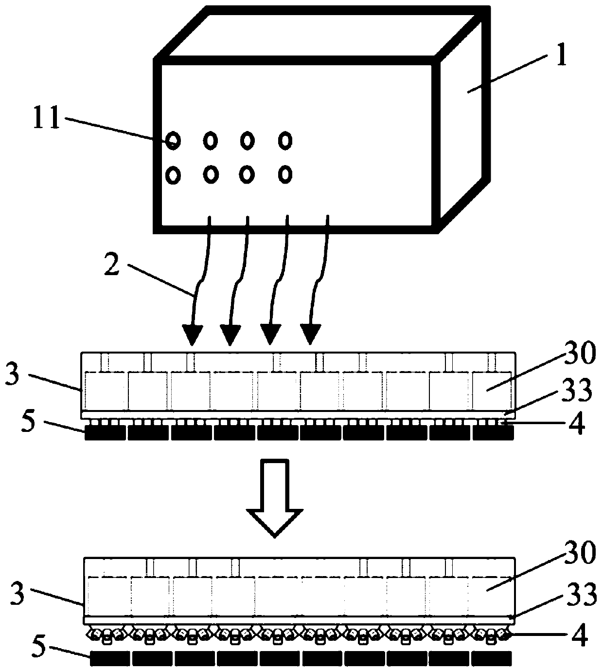
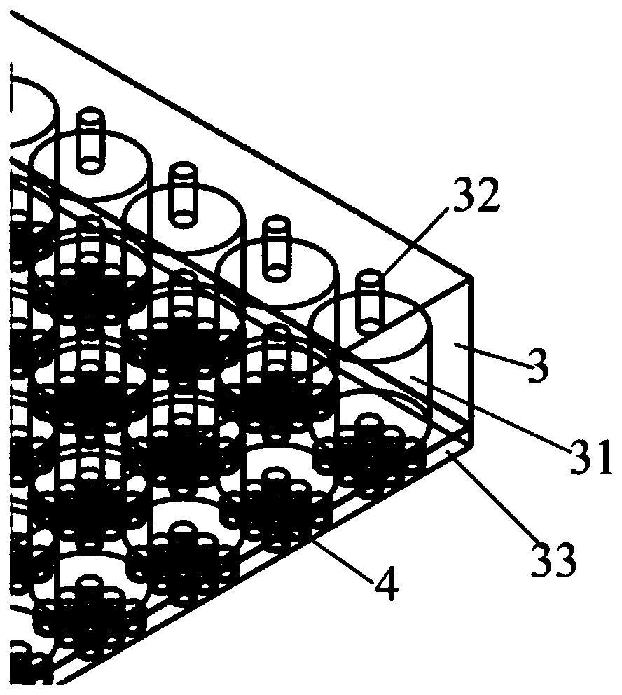
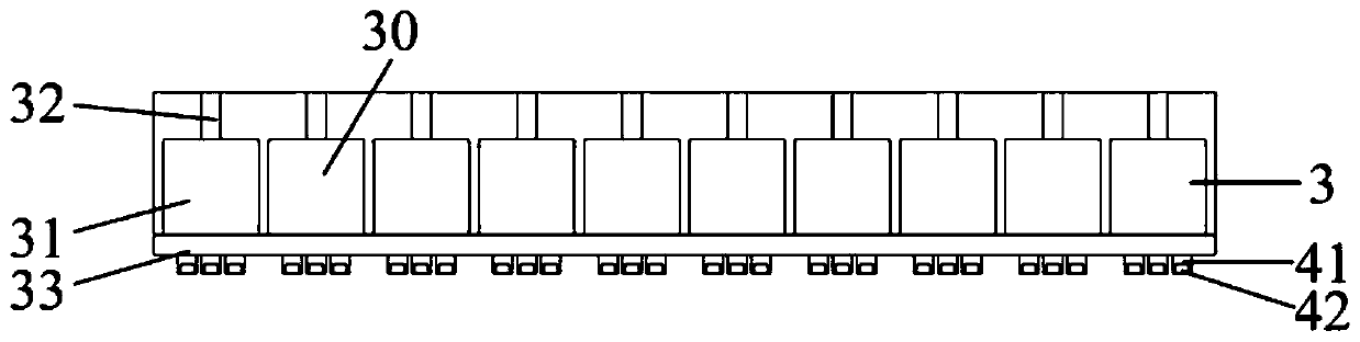
[0041] Such as Figure 1 to Figure 10 As shown, the present disclosure provides a stylized transfer printing device based on a bionic structure, which has an electronic control module 1, an air pipe 2, a stamp base 3 and a suction cup assembly 4, and the suction cup assembly 4 is used to attract the object 5 to be transferred .

[0042] The stamp base 3 is formed with an air chamber 30 , the air tube 2 is connected to the air chamber 30 , a part of the air chamber wall of the air chamber 30 is formed by a film 33 , and the suction cup assembly 4 is connected to the film 33 o...


PUM


Abstract

The invention provides a bionic structure-based programmable transfer device. The bionic structure-based programmable transfer device comprises an air chamber and a suction disc assembly, wherein a part of an air chamber wall of the air chamber is formed by a thin film, the thin film is blown up towards the exterior of the air chamber when air pressure in the air chamber becomes larger, the suction disc assembly is connected to the thin film and is used for sucking a transferred object, the contact area of the suction disc assembly and the transferred object becomes smaller when the thin filmis blown up, so that the transferred object can be disconnected with the suction disc assembly. By the transfer device, continuous and effective control of an interface adhesive force can be achieved,and large-scale transfer and programmable transfer can be achieved.

Description

technical field [0001] The invention relates to the technical fields of engineering materials, structural design, mechanical bionics and electronic information, and in particular to a stylized transfer printing device based on a bionic structure. Background technique [0002] Transfer printing technology plays a pivotal role in the preparation of flexible electronic devices. The traditional micro-nano electronic preparation process can be used to prepare the inorganic functional part on the silicon wafer, and then use the transfer step to peel off the inorganic functional part from the silicon wafer and print it. On the flexible substrate, the inorganic functional part is integrated and packaged with the flexible substrate to form an inorganic flexible electronic device. [0003] This process involves the adhesion and debonding (peeling) of the interface of different materials. In order to better complete this process, different scholars have proposed various transfer metho...

Claims


Application Information

Patent Timeline
Patent Type & Authority Patents(China)
IPC IPC(8): H01L21/67H01L21/683
CPCH01L21/67144H01L21/6838
Inventor 冯雪李航飞
Owner TSINGHUA UNIV
Why Eureka
Try Eureka