
A Strong Field Mode Filter Existing Only tm Mode

A filter and mode technology, which is applied to waveguide devices, modification through conduction heat transfer, cooling/ventilation/heating transformation, etc., can solve microwave system failures, reduce waveguide power capacity, increase the probability of system ignition failure, etc. question

Inactive Publication Date: 2020-10-27
INST OF ELECTRONICS ENG CHINA ACAD OF ENG PHYSICS
View PDF7 Cites 0 Cited by
  • Summary
  • Abstract
  • Description
  • Claims
  • Application Information

AI Technical Summary

Problems solved by technology

The first method usually reduces the radius of the waveguide to filter out all the miscellaneous modes whose cutoff frequency is higher than the operating frequency of the TM01 mode, such as the TE21 mode filtering method in the aforementioned rotary joint, its disadvantage is that the radius of the waveguide becomes smaller, which in turn will The power capacity of the waveguide is reduced, and the probability of system ignition failure is increased; in the second method, the miscellaneous mode field is reflected in the system and not output, such as the TE11 mode filtering method in the aforementioned rotary joint, its disadvantage is that it is reflected back and forth Microwaves are easy to damage other microwave devices; at the same time, the above two methods are only effective for some specific miscellaneous modes, but not for all miscellaneous modes; in contrast, using dielectric loading to efficiently absorb and consume miscellaneous modes can Guarantee the power capacity, stability and reliability of the system, and have great application advantages, such as the aforementioned electric vacuum tube source, but the conventional medium-loaded absorption and dissipation method absorbs and consumes miscellaneous modes, and at the same time, there is no need for selective absorption and consumption. Working in TM mode, which does not meet the electrical performance index requirements for low insertion loss in the working mode; at the same time, when the system works in the strong field TM mode, the power of the TM mode and the mixed mode dissipated by the medium is extremely large, which easily leads to the temperature of the loading medium Too high, which will lead to microwave system failure

Method used


Image

  • A Strong Field Mode Filter Existing Only tm Mode
  • A Strong Field Mode Filter Existing Only tm Mode

Examples


Embodiment 1

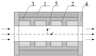
[0036] In the large bandwidth range of 27-42GHz, the insertion loss of TM01 mode and TM11 mode is less than 0.12dB, while the insertion loss of TE11 mixed mode field is greater than 0.5dB, and the insertion loss of TE21 mixed mode field is greater than 1.72dB. The schematic diagram of its structure is as follows figure 2 shown.

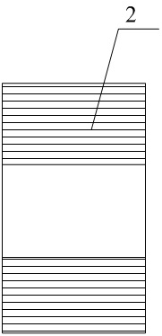
[0037] The device used in this example is highly oriented pyrolytic graphite with resistivity anisotropy, such as figure 1 As shown, the wall thickness in the r direction is 2mm, and the length in the z direction is 200mm; the resistivity in the z direction is 3.5~4.5×10 -7 Ω.m, close to 2.22×10 of platinum metal -7 Ω.m, with good electrical conductivity; the resistivity in the angular direction is 1.5~2.5×10 -3 Ω.m, which can effectively attenuate the wall current; the thermal conductivity in the Z direction is 1600-2000W / m.k, which is much higher than the 200W / m.k of duralumin. The material can work at high temperature, the hardest at 2750°C, an...


PUM


Abstract

The invention discloses a strong field mode filter only with a TM mode. The strong field mode filter comprises a hollow structure composed of a parasitic mode absorption component and a heat dissipation component. The parasitic mold absorption component comprises connecting flanges at both ends and a resistivity anisotropic component disposed between the connecting flanges. The heat dissipation component includes a casing and a heat sink on the outside the casing. The resistivity anisotropic component is disposed inside the casing in the axial direction. In the TM mode, a loss characteristic is present in the angular direction and the resistivity is much larger than the axial resistivity, and a good conductor is present in the axial direction. The strong field mode filter uses the resistivity anisotropic material to filter out all non-TM modes, has a high power capacity and filters out all non-TM mode parasitic modes. Based on the strong field mode filter, it is possible to carry out mode field control in electronic vacuum device such as a virtual cathode oscillator (VCO), a relativistic back wave tube (RBWO), and a relativistic magnetron or a strong field radar system rotating joint, thereby laying a certain technical foundation for promoting the development of microwave millimeter wave related technology.

Description

technical field [0001] The present invention relates to the field of microwave and millimeter wave technology, and specifically refers to a mode filter working under strong field strength, which can attenuate and filter out input non-TM mode microwave signals, and save only TM mode for low-loss transmission. Background technique [0002] With the development of microwave source technology, the microwave system is developing towards higher frequency and stronger field strength, and the transmission guided wave system has also changed from coaxial waveguide and rectangular waveguide to over-molded circular waveguide with higher power capacity. [0003] The high-order wave type TM01 mode transmitted in the circular waveguide has an electric field perpendicular to the circumference and is rotationally symmetric, and has a stable phase, so it becomes a strong-field millimeter-wave source, such as a virtual cathode oscillator (VCO), a relativistic return wave tube (RBWO), and a rel...

Claims


Application Information

Patent Timeline
Patent Type & Authority Patents(China)
IPC IPC(8): H01P1/207H05K7/20
CPCH01P1/207H05K7/2039
Inventor 薛长江郑贵强任家怡陈代兵赵柳蒋里芳吴尚昀
Owner INST OF ELECTRONICS ENG CHINA ACAD OF ENG PHYSICS
Learn More