Eureka AIR delivers breakthrough ideas for toughest innovation challenges, trusted by R&D personnel around the world.

Diesel engine post-processing device

A post-processing device and diesel engine technology, applied in the electronic control of exhaust treatment devices, diagnostic devices of exhaust treatment devices, exhaust treatment, etc., can solve the problem of low catalyst conversion efficiency and achieve the effect of improving catalytic conversion efficiency

Inactive Publication Date: 2019-07-05
HENAN UNIV OF SCI & TECH
View PDF17 Cites 4 Cited by
  • Summary
  • Abstract
  • Description
  • Claims
  • Application Information

AI Technical Summary

Problems solved by technology

[0005] The purpose of the present invention is to provide a diesel engine aftertreatment device for solving the problem of low catalyst conversion efficiency in the prior art when the exhaust gas temperature is low

Method used


Image

  • Diesel engine post-processing device
  • Diesel engine post-processing device
  • Diesel engine post-processing device

Examples


Embodiment 1

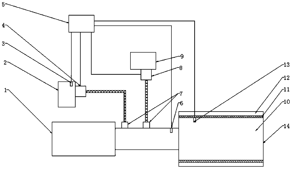
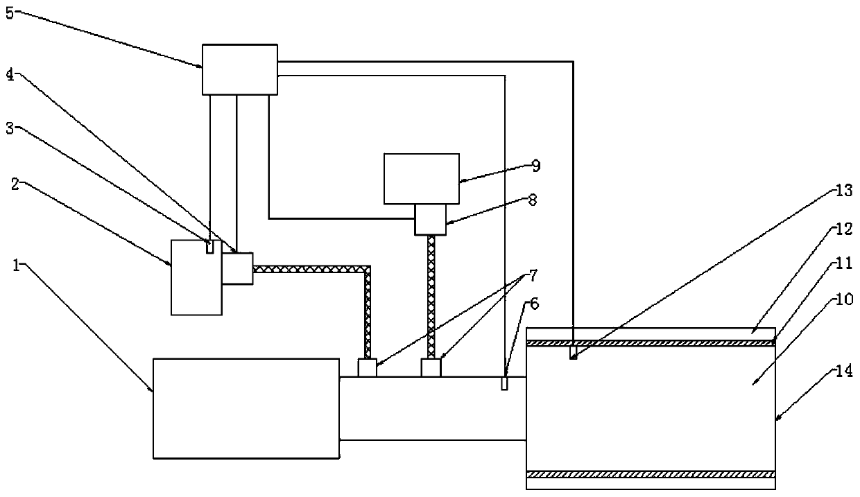
[0022] like figure 1 The diesel engine post-treatment device shown includes a DPF chamber 1 and an SCR catalyst chamber 14, and the exhaust passage between the DPF chamber 1 and the SCR catalyst chamber 14 is equipped with a water jet to the exhaust passage. and two nozzles 7 for urea solution, each nozzle 7 is connected with a separate liquid supply pipeline, one of which is equipped with a metering pump 4 and a water tank 2, and the other is equipped with a selective catalytic reduction for SCR urea pump 8 and urea tank 9.

[0023] The SCR catalyst chamber 14 is provided with a catalyst carrier 10. In order to ensure the catalytic effect, the catalyst carrier 10 is cylindrical. The heater is a PTC heater wrapped around the catalyst carrier 10, and the surface of the tubular electric heater is coated with an insulating layer.

[0024] A thermal insulation cavity 12 is provided between the cylindrical electric heater 11 and the housing of the SCR catalytic converter chamber ...

Embodiment 2

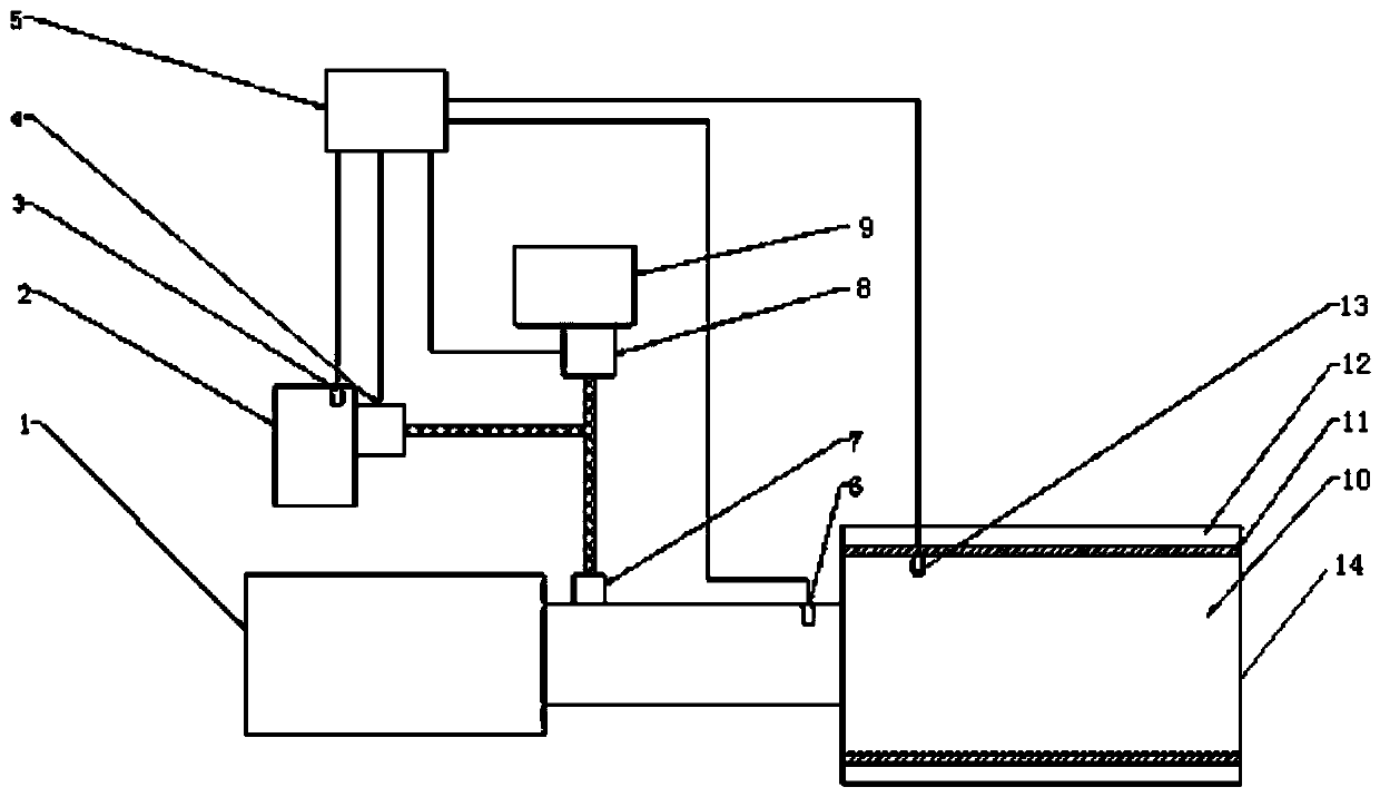
[0052] like figure 2 Another diesel engine post-processing device is shown. On the basis of the diesel engine post-processing device in the first embodiment of the device, the liquid supply pipeline connected to the nozzle 7 includes a main road, which communicates with the water supply branch of the main road and the urea branch. A metering pump 4 and a water tank 2 are provided on the water supply branch, a urea pump 8 and a urea tank 9 are provided on the urea branch, and the controller 5 controls and connects the urea pump 8 . The controller 5 controls the amount of water sprayed by the water tank 2 into the channel through the metering pump 4, and the amount of urea solution sprayed into the channel by the urea tank 9 through the urea pump 8. After the two are mixed in the pipeline, they are sprayed into the exhaust gas pipe to reduce the exhaust temperature.

[0053] When the diesel engine is running at high speed and heavy load or before SCR and DPF regeneration, the ...


PUM


Abstract

The invention relates to a diesel engine post-processing device, and belongs to the technical field of internal combustion engine post-processing. The diesel engine post-processing device comprises aDPF chamber and an SCR catalyst chamber; a channel, between the DPF chamber and the SCR catalyst chamber, is provided a nozzle which is used for injecting into the channel; the nozzle is connected toa liquid supply pipeline; and a catalyst carrier is arranged in the SCR catalyst chamber, and an electric heater is arranged on the periphery of the catalyst carrier. When the diesel engine is cold started or runs at a low rotating speed and a low load, the arranged tubular electric heater is used for heating a catalyst, so that the purpose of comprehensively improving the catalytic conversion efficiency of the catalyst is achieved. In addition, when the exhaust temperature is too high, water can be sprayed into the channel through the liquid supply pipeline and the nozzle, so that the coolingeffect is achieved, and the catalyst is prevented from losing effect.

Description

technical field [0001] The invention belongs to the technical field of post-processing of internal combustion engines, and in particular relates to a post-processing device for diesel engines. Background technique [0002] The main pollutant emitted by diesel engine combustion is NO X and PM, x=1,2, in order to avoid the pollution caused by the emission of pollutants, the diesel engine exhaust after-treatment system has become one of the indispensable systems of the engine. Many of them use SCR (Selective Catalytic Reduction, Selective Catalytic Reduction) to reduce NO X emissions, but the conversion efficiency of the SCR catalyst is very dependent on the temperature range, commonly used vanadium-based, copper-based, iron-based and molecular sieve catalysts have their allowable operating temperature range. During the use of the diesel engine, when the diesel engine is running at high speed and high load or when the DPF (Diesel Particulate Filter, diesel particulate filter)...

Claims


Application Information

Patent Timeline
Patent Type & Authority Applications(China)
IPC IPC(8): F01N3/035F01N3/20F01N3/28F01N11/00F01N13/14
CPCF01N3/035F01N3/2013F01N3/2066F01N3/2803F01N11/002F01N13/14F01N2570/14F01N2610/02Y02T10/12Y02T10/40
Inventor 李民张振方刘建新杜慧勇王站成苗家轩徐斌
Owner HENAN UNIV OF SCI & TECH
Why Eureka
Eureka Blog
Learn More