Manufacturing method for composite member
A manufacturing method and technology for composite parts, applied in the field of composite parts manufacturing, can solve problems such as interface peeling and inability to bond
- Summary
- Abstract
- Description
- Claims
- Application Information
AI Technical Summary
Problems solved by technology
Method used
Image

Examples
Embodiment 1
[0058] (1) Prepare the organosilicon material in the following manner. To 100 parts by mass of liquid silicone rubber (vinyl group-containing dimethyl polysiloxane: manufactured by Gelest, "DMS-V35"), add 1 part by mass of p-styryltrimethoxy as an adhesive component. base silane (manufactured by Shin-Etsu Chemical Co., Ltd.), and mixed for 30 minutes by a planetary mixer. To this mixture, 4 parts by mass of a hydrosilane crosslinking agent (hydrosilyl group-containing dimethylpolysiloxane: manufactured by Gelest, "HMS-151") was added and further mixed for 30 minutes, and then the pressure was reduced. Degassing, thereby preparing a liquid silicone material.
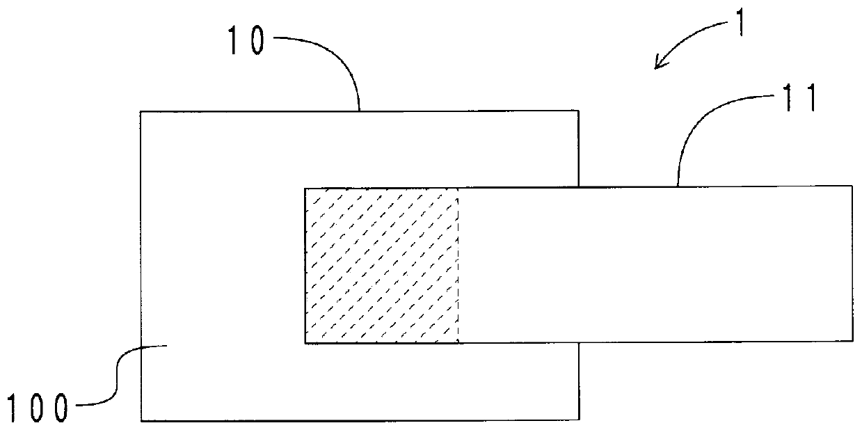
[0059] (2) A rectangular plate-shaped member (aluminum die-casting member) produced by die-casting ADC12 of an Al—Si—Cu-based alloy was prepared. The size of the plate-shaped member was 60 mm on the long side, 45 mm on the short side, and 2.0 mm in thickness.
[0060] First, laser processing was performed on the entire...
Embodiment 2
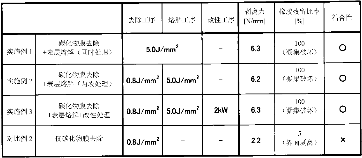
[0064] A test piece was produced in the same manner as in Example 1 with respect to the entire one surface of the same plate-shaped member as in Example 1, except that the conditions were changed and secondary laser processing was performed. The conditions for the first laser treatment are moving speed: 400mm / sec, laser irradiation density: 0.8J / mm 2 , the conditions for the second laser treatment are moving speed: 100mm / sec, laser irradiation density: 5.0J / mm 2 . The first laser treatment corresponds to the removal process in the present invention, and the second laser treatment corresponds to the melting process in the present invention.
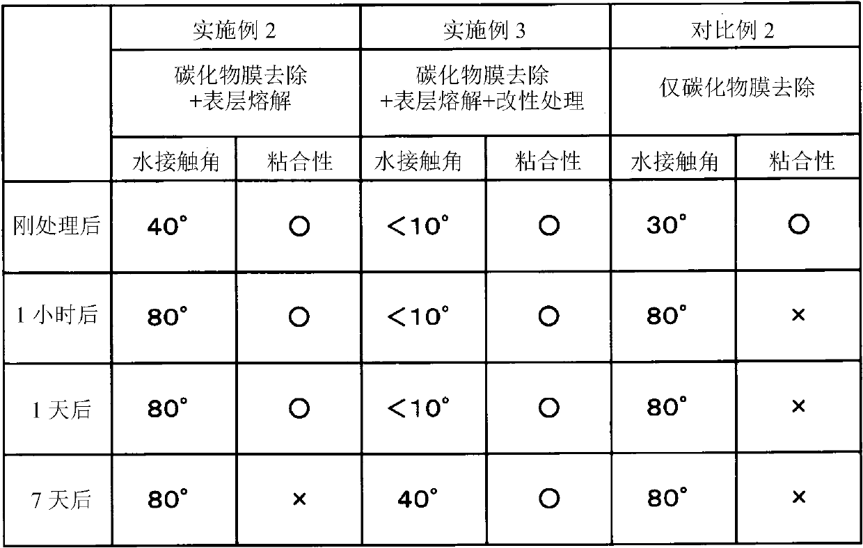
[0065] In Example 2, a plurality of similarly laser-processed plate-shaped members were produced, and immediately after and after laser-processing (melting process) was performed using the above-mentioned plurality of plate-shaped members, as described later. The water contact angle of the laser-processed surface was measured every time ...
Embodiment 3
[0067] In the same manner as in Example 2, a test piece was prepared in the same manner as in Example 1, except that the entire one surface of the plate-shaped member was subjected to secondary laser processing, and then microwave plasma treatment was further performed in a vacuum. Microwave plasma treatment was performed as follows. First, the plate-shaped member is arranged in a vacuum container, and the inside of the vacuum container is brought into a reduced pressure state of 0.5 Pa or less. Next, oxygen gas was supplied into the vacuum vessel to form an oxygen atmosphere at a pressure of 10 Pa. In this state, microwave plasma was generated at a frequency of 2.45 GHz and an output of 2 kW, and irradiated for 10 seconds on the entire one surface of the plate-shaped member that had undergone laser processing. In this way, the one surface is activated to generate hydroxyl groups on the surface. The microwave plasma treatment in Example 3 corresponds to the modification proc...
PUM
| Property | Measurement | Unit |
|---|---|---|
| diameter | aaaaa | aaaaa |
Abstract
Description
Claims
Application Information
 - R&D
- Intellectual Property
- Life Sciences
- Materials
- Tech Scout
- Unparalleled Data Quality
- Higher Quality Content
- 60% Fewer Hallucinations
Browse by: Latest US Patents, China's latest patents, Technical Efficacy Thesaurus, Application Domain, Technology Topic, Popular Technical Reports.
© 2025 PatSnap. All rights reserved.Legal|Privacy policy|Modern Slavery Act Transparency Statement|Sitemap|About US| Contact US: help@patsnap.com