
Low frequency degaussing power supply for power transformer

A low-frequency, power supply technology, applied in the field of transformer low-frequency degaussing power supply, can solve the problem of not easy to obtain power supply, achieve good degaussing effect, high-efficiency degaussing, and volume reduction

Inactive Publication Date: 2019-06-14
SUZHOU INDAL PARK HAIWO TECH
View PDF5 Cites 4 Cited by
  • Summary
  • Abstract
  • Description
  • Claims
  • Application Information

AI Technical Summary

Problems solved by technology

Due to the high working voltage of large-scale transformer windings, the degaussing voltage required for degaussing often reaches tens of thousands of volts or even hundreds of thousands of volts. to be able to meet the conditions
The DC degaussing method has the advantage of small size, and is often used in the on-site degaussing of transformers. However, there is still a certain gap in the effect of DC degaussing compared with AC degaussing. The remanence of DC degaussing is larger than that of AC degaussing.

Method used


Image

  • Low frequency degaussing power supply for power transformer
  • Low frequency degaussing power supply for power transformer

Examples


Embodiment Construction

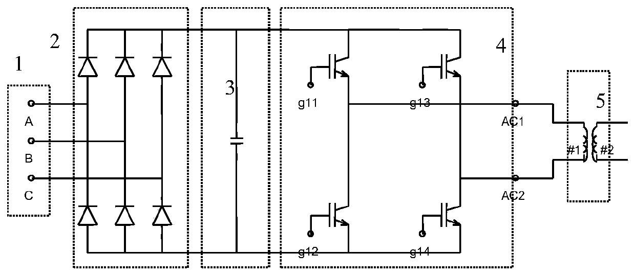
[0020] Such as figure 2 As shown, a low-frequency degaussing power supply includes a three-phase AC power supply 1, a three-phase bridge rectifier circuit 2, a filter circuit 3, and a bridge low-frequency inverter circuit 4, wherein the three-phase AC power supply and the three-phase bridge rectifier circuit The input end of the three-phase bridge rectifier circuit is connected to the input end of the filter circuit, the output end of the filter circuit is connected to the input end of the bridge low frequency inverter circuit, and the bridge low frequency inverter circuit The output terminal is connected to the primary side of the transformer 5 .

[0021] The three-phase bridge rectifier circuit 2 consists of six diodes of the same type.

[0022] The filter circuit 3 is a filter capacitor.

[0023] The bridge-type low-frequency inverter circuit 4 is a single-phase bridge-type low-frequency inverter, which is composed of four triodes of the same type.

[0024] The controll...


PUM


Abstract

The invention relates to a low frequency degaussing power supply. The low frequency degaussing power supply is characterized by comprising a three-phase alternating current power supply, a three-phasebridge rectifier circuit, a filter circuit, a bridge low frequency inverter circuit. The three-phase alternating current power supply is connected with an input end of the three-phase bridge rectifier circuit. An output end of the three-phase bridge rectifier circuit is connected with an input end of the filter circuit. The output end of the filter circuit is connected with the input end of the bridge low frequency inverter circuit. The output end of the bridge low frequency inverter circuit is connected with a primary side of a transformer. According to the low frequency degaussing power supply, degaussing is carried out through adoption of the low frequency power supply. Compared with power frequency degaussing, the power supply has the advantage that a size is greatly reduced. A degaussing effect reaches a level of alternating current degaussing. The degaussing effect is good. An equipment size is small. Efficient degaussing of a large-scale power transformer can be realized.

Description

technical field [0001] The invention belongs to the technical field of electric equipment, and in particular relates to a transformer low-frequency degaussing power supply. Background technique [0002] During the use of large-scale power transformers, due to various reasons, there is a phenomenon of unidirectional magnetization of the iron core. The residual magnetism generated by unidirectional magnetization will increase the noise and iron loss of the transformer during operation, and bring hidden dangers to the safe operation of the transformer. Therefore, when there is residual magnetism in the transformer, it should be demagnetized. Conventional degaussing methods are: power frequency power degaussing method, DC degaussing method. Due to the high working voltage of large-scale transformer windings, the degaussing voltage required for degaussing often reaches tens of thousands of volts or even hundreds of thousands of volts. to meet the conditions. The DC degaussing ...

Claims


Application Information

Patent Timeline
Patent Type & Authority Applications(China)
IPC IPC(8): H02M5/458H01F13/00
Inventor 葛凯盛志平
Owner SUZHOU INDAL PARK HAIWO TECH
Learn More