Multi-lens grinding vessel jig

A lens and jig technology, applied in the direction of grinding machines, manufacturing tools, optical surface grinders, etc., can solve the problems of product shape and size errors, low production efficiency, high yield, etc., to reduce intervention, shorten process time, and improve production efficiency and the effect of product yield

Inactive Publication Date: 2019-06-11
江苏洪诚健康科技有限公司
View PDF3 Cites 0 Cited by
  • Summary
  • Abstract
  • Description
  • Claims
  • Application Information

AI Technical Summary

Problems solved by technology

[0003] Aiming at the requirements of the above-mentioned multi-piece lens processing, the present invention provides a multi-piece lens grinding dish fixture, which aims to solve the problems of low production efficiency, large error in product shape size and low yield rate in the production of camera lens in the prior art. The problem

Method used


Image

  • Multi-lens grinding vessel jig

Examples


Embodiment Construction

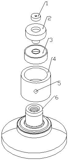
[0014] Depend on figure 1 As shown, the multi-piece abrasive dish fixture for the lens, the honeycomb dish 6 of the working part is installed on the white plastic steel nut 4, and the white plastic steel nut has a nut hole 5, which is convenient for the honeycomb dish 6 to take. The extension of the 608 bearing 3 is installed on the The upper end of the white plastic steel nut 4 and the 608 bearing 3 are internally installed on the protruding part of the copper utensil 2, and the nickel alloy terminal 1 is installed on the copper utensil 2. The nickel alloy terminal 1 is installed on the working rod of the machine table. After the machine is turned on, the working shaft drives the honeycomb dish of the working part to rotate, and the upper part is pressed on the nickel alloy terminal by the tip of the string rod, so that the entire bearing screw cap will rotate rapidly following the operation of the working shaft, so that there will be no honeycomb The 6 rotations of the dish...


PUM


Abstract

A multi-lens grinding vessel jig comprises a nickel alloy terminal, a copper appliance, a 608 gearing, a white plastic steel nut, a nut hole and a work portion honeycomb vessel, and is characterized in that in the bearing type nut, the white plastic steel nut is used for replacing an iron nut. The multi-lens grinding vessel jig replaces a profiling machine and an edge chamfering machine in the traditional technology for operation of profiling and edge chamfering, and manual intervention is reduced; and by means of precision of CNC equipment, the procedures of profiling and edge chamfering arecompleted at a time on a lens material through a CNC tool, on the premise of guaranteeing the product appearance size, the product production process time is shortened, and the production efficiency and product yield are increased.

Description

technical field [0001] The invention relates to the technical field of lens production, in particular to a jig and a method for processing camera lenses using the jig. Background technique [0002] Profiling refers to the manual operation of profiling machines to cut semi-finished products (generally larger in size than finished lenses) to the required specifications of finished products, usually with an error of ±0.05mm. Beveling refers to the semi-finished product after profiling, and the edge of the product is beveled to the required specifications of the finished product through manual operation of the beveling machine, usually with an error of ±0.1mm. The profiling and edge beveling process can easily cause product chipping (collapsing refers to the damage of the edge of the product). Moreover, profiling and beveling must be produced by manual profiling machines and beveling machines. One machine per person, on the one hand, the production efficiency is low, and on the...

Claims


Application Information

Patent Timeline
Patent Type & Authority Applications(China)
IPC IPC(8): B24B41/04B24B13/01
Inventor 叶利民
Owner 江苏洪诚健康科技有限公司
Why Eureka
Try Eureka