Elastic pipe bundle vibration reinforced heat exchange solar cavity heat absorber

A technology of tube bundle vibration and enhanced heat exchange, applied in the direction of solar collectors, components of solar collectors, solar thermal energy, etc. The problems of high focused energy density on the tube surface and limited flow heat transfer capacity in the tube can improve safety and heat transfer performance, improve flow heat transfer performance, and improve working life and reliability.

Pending Publication Date: 2019-05-28
HUNAN UNIV OF SCI & TECH
View PDF0 Cites 1 Cited by
  • Summary
  • Abstract
  • Description
  • Claims
  • Application Information

AI Technical Summary

Problems solved by technology

Traditional heat absorbers usually install metal coils (heat exchange of working medium in the tube) in the cavity structure. Due to the high energy density and uneven distribution on the surface of the metal tube, and the limited heat transfer capacity of the flow in the tube, it usually leads to heat absorption. High-temperature hot spots or large temperature gradients are formed in the device, resulting in significant thermal stress, thermal deformation and burning damage, especially the problem of forced shutdown due to working fluid leakage after the metal tube wall is perforated, all of which directly affect the heat absorption The light-to-heat conversion efficiency, operational safety and working life of the device

Method used


Image

  • Elastic pipe bundle vibration reinforced heat exchange solar cavity heat absorber
  • Elastic pipe bundle vibration reinforced heat exchange solar cavity heat absorber
  • Elastic pipe bundle vibration reinforced heat exchange solar cavity heat absorber

Examples


Embodiment 1

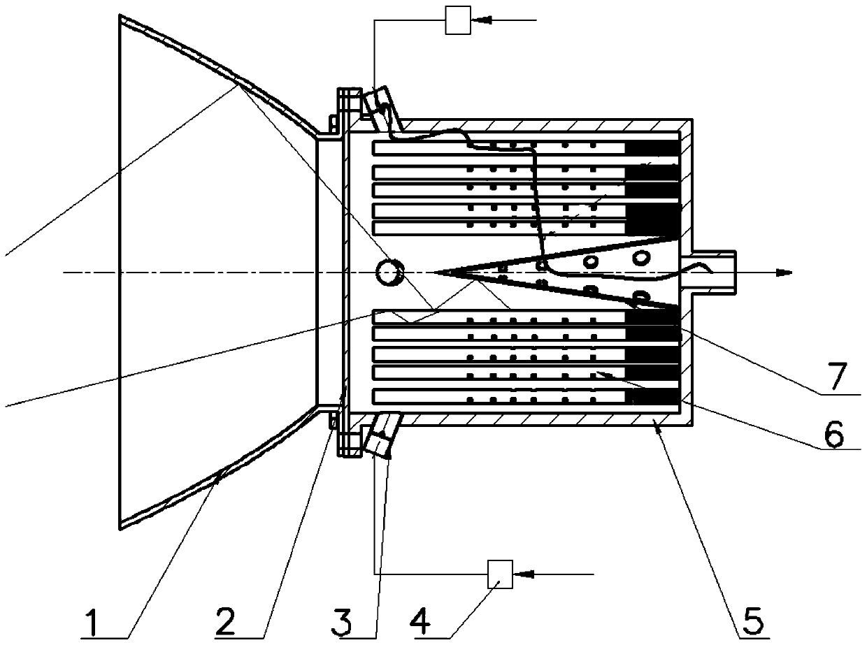
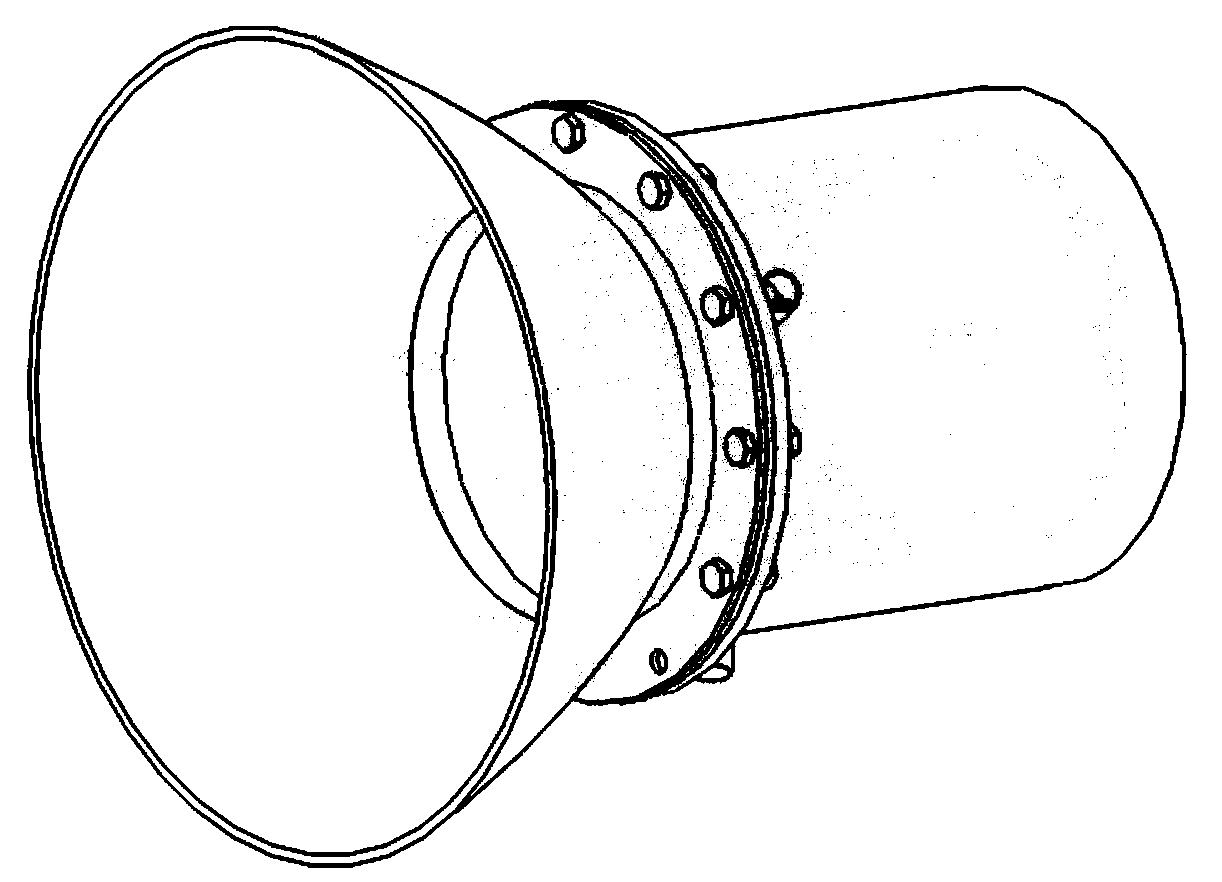
[0032] like figure 1 As shown, Embodiment 1 of the present invention includes a secondary concentrator 1 , a glass plate 2 , a pulsating flow generator 3 , a metal cavity 5 , an elastic tube bundle 6 , a deflector 7 and an on-off valve 4 . The metal cavity 5 is a cylindrical structure, or a cylindrical structure with a quadrangular, triangular, or elliptical cross-section, and a flange is provided at the front end. The secondary concentrator 1 and the glass plate 2 are installed at the front opening of the metal cavity 5 through a flange, the glass plate 2 is located between the secondary concentrator 1 and the metal cavity 5, and the secondary concentrator 1 is used In order to continue to gather the received solar energy into the heat absorber, the cross-section of the inner surface of the secondary concentrator 1 is parabolic, and the inner surface is a specular reflective wall.

[0033] The bottom of the metal cavity 5 is provided with a through hole. like figure 2 As ...

Embodiment 2

[0038] like Figure 6 As shown, the structure of Embodiment 2 of the present invention is similar to that of Embodiment 1, mainly that the internal structure of the deflector 7 and the metal cavity 5 is different from that of Embodiment 1. details as follows:

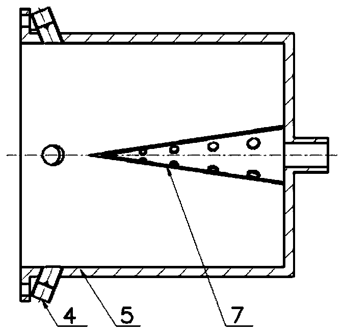
[0039] like Figure 6 As shown, the deflector 7 is a hollow cylindrical structure, the end of the deflector 7 is concave tapered, and a number of through holes are provided on the side wall of the deflector 7 . The deflector 7 is fixed on the bottom of the metal cavity 5 by welding, and the inner cavity of the deflector 7 communicates with the through hole at the bottom of the metal cavity 5 .

[0040] like Figure 7 , 8 As shown, the metal cavity 5 is provided with a plurality of partitions 12; the partitions 12 are sequentially connected to the bottom of the metal cavity 5, the inner wall surface and the outer wall surface of the deflector 7, the described The height of the deflector 7 and the partition plate 12 ...


PUM


Abstract

The invention discloses an elastic pipe bundle vibration reinforced heat exchange solar cavity heat absorber. The elastic pipe bundle vibration reinforced heat exchange solar cavity heat absorber comprises a secondary light condenser, a pulsating flow generator, a metal cavity, elastic pipe bundles, a glass plate and a guider; the metal cavity is of a cylindrical structure; the secondary light condenser and the glass plate are mounted in a front end opening of the metal cavity; the glass plate is positioned between the metal cavity and the secondary light condenser; a through hole is formed inthe bottom of the metal cavity; the guider is of a hollow structure, and is provided with a through hole in the side wall; the guider is fixed at the bottom of the metal cavity; an inner cavity of the guider communicates with the through hole in the bottom of the metal cavity; multiple elastic pipe bundles are welded at the bottom of the metal cavity; and the pulsating flow generator is mounted on the front end side wall of the metal cavity. Through the pulsating flow generator, the multiple elastic pipe bundles are vibrated, so that the heat exchange performance can be improved; and the problem of working medium leakage caused by high-temperature hot spot ablation of a traditional heat absorber can be solved, so that the working life and the reliability are greatly improved.

Description

technical field [0001] The invention belongs to the technical field of solar energy concentrating and heat collecting equipment, in particular to a solar cavity heat absorber of elastic tube bundle vibration enhanced heat exchange type. Background technique [0002] Solar energy is a renewable energy that is clean, environmentally friendly, adequately supplied, and widely distributed. Concentrating solar thermal power generation systems can be organically combined with heat storage systems or conventional thermal power stations to achieve continuous and stable power generation. It is an important way to solve the problems of energy shortage and environmental pollution. Concentrating solar thermal power generation technology gathers sunlight energy to the surface of the heat absorber through a large-area concentrator and heats the internal fluid working medium, and then drives the generator set to generate electricity through a thermodynamic cycle process. It is one of the im...

Claims


Application Information

Patent Timeline
Patent Type & Authority Applications(China)
IPC IPC(8): F28F1/02F28F9/24F24S70/20F24S10/70F24S80/00
CPCY02E10/44
Inventor 颜健彭佑多叶笑洋刘永祥
Owner HUNAN UNIV OF SCI & TECH
Why Eureka
Try Eureka