
A high temperature superconducting motor

A high-temperature superconducting and superconducting magnet technology, applied in electromechanical devices, electrical components, electric components, etc., can solve the problems of low support of all-composite materials, increase the difficulty of manufacturing, and large circumferential displacement of the coil, and improve the rigidity of the rotor. and operational stability, reducing manufacturing difficulty and material cost, and increasing power density

Active Publication Date: 2020-08-07
WUHAN MARINE ELECTRIC PROPULSION RES INST CHINA SHIPBUILDING IND CORP NO 712 INST
View PDF4 Cites 0 Cited by
  • Summary
  • Abstract
  • Description
  • Claims
  • Application Information

AI Technical Summary

Problems solved by technology

There are a variety of air gap armature structure schemes in the prior art, some of which use all-composite support to support the stator coil and transmit torque, but the stiffness of the all-composite support is low, resulting in large circumferential displacement of the coil, causing Vibrates and damages the insulation; some use a combination of stainless steel teeth and composite material pads to fix the coil. Although the rigidity has been improved, the processing cost is expensive, and the installation process is complicated, which increases the difficulty of manufacturing

Method used


Image

  • A high temperature superconducting motor
  • A high temperature superconducting motor
  • A high temperature superconducting motor

Examples


Embodiment 1

[0024] Such as Figure 1 to Figure 5 Shown is a basic embodiment of the invention.

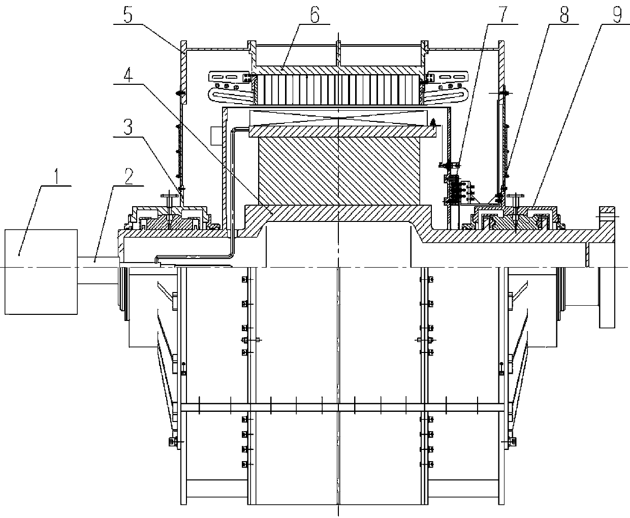
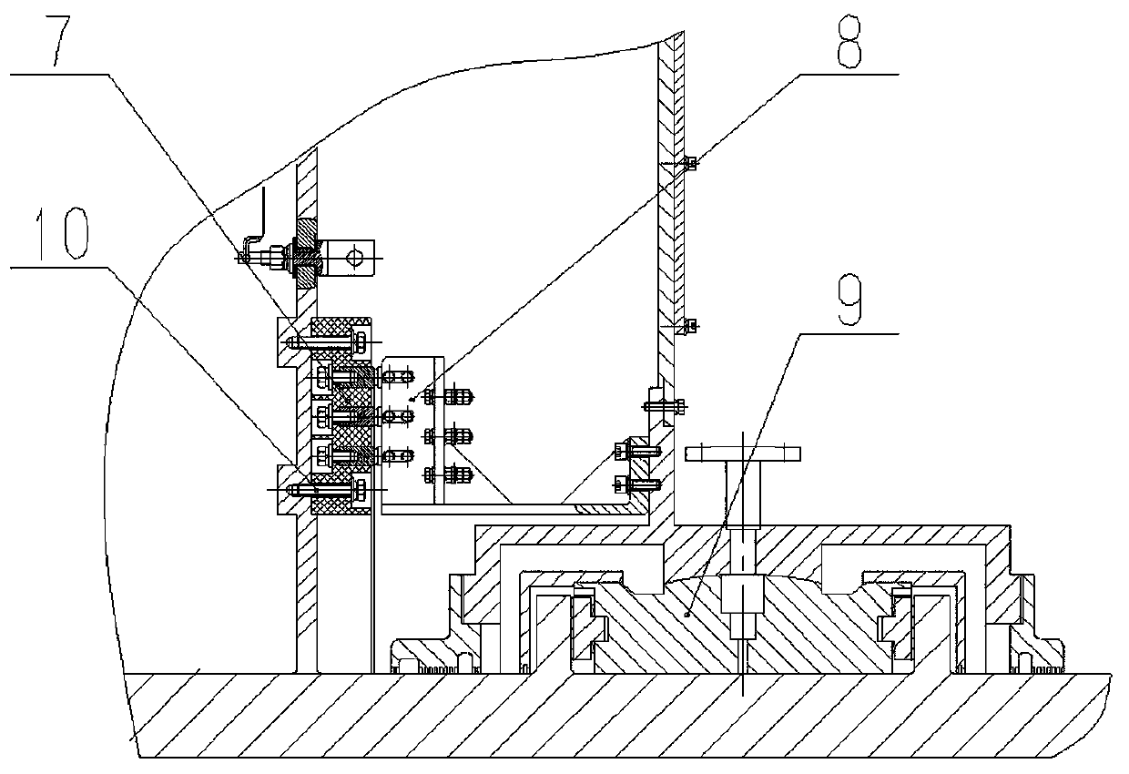
[0025] A high-temperature superconducting motor, comprising a low-temperature refrigeration system 1, a refrigerant transmission coupling device 2, a non-drive end bearing housing 3 and bearings, a rotor 4, an end cover 5, a stator 6, a disc collector ring 7, and a brush holder with electric brushes 8. The driving end bearing seat 9 and the bearing etc. are composed.

[0026] The stator 6 adopts an air-gap armature structure without iron teeth, and is composed of a machine base, an iron core punch 61, a wedge key 62, a coil fixing part 63, a stator coil 64 and a slot wedge 65, and the coil fixing part 63 is an embedded The glass fiber composite material block 622 of the stainless steel metal plate 621, the stator coil 64 can adopt a single-layer transposition coil structure, the coil fixing part 63 is placed in the dovetail slot of the iron core punch 61, and is fixed by wedge-shaped key 62 e...

Embodiment 2

[0030] The difference from Embodiment 1 is that the coil fixing member 63 is a glass fiber composite material block 622 embedded with a high-strength aluminum alloy plate.

Embodiment 3

[0032] The difference from Embodiment 1 is that the stator armature winding adopts a double-layer transposition coil structure.


PUM


Abstract

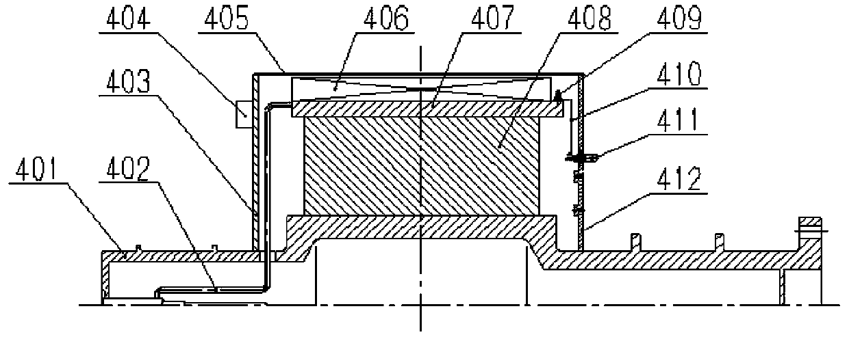
The invention discloses a high-temperature superconducting motor. The high-temperature superconducting motor comprises a low-temperature refrigeration system, a refrigerant transmission coupling device, a non-drive end bearing seat, a bearing, a rotor, an end cover, a stator, a disk collecting ring, a brush holder, a drive end bearing and a bearing. The stator is formed by a base, a core punch, awedge key, a coil fixing member, a stator coil and a groove, the coil fixing member is a glass fiber composite material block embedded with a stainless steel metal plate and is put into a dove tail groove of the core punch to be fastened by the wedge key; the rotor is formed by a rotation shaft, a refrigerant transmission pipe, a shielding layer, a superconducting magnet, a low temperature skeleton and a supporting heat insulating device; the refrigerant generated by the low-temperature refrigeration system cools the low temperature skeleton, and then a conducting mode is employed to cool thesuperconducting magnet; and moreover, the high-temperature superconducting motor is specially suitable for application in a high-temperature superconducting motor or a high-temperature superconductingdirect-driven wind turbine generator for propulsion of ships with the requirements of large power, low rotation speeds, compact structures and low operation cost.

Description

technical field [0001] The invention belongs to the field of motors, in particular to a high-temperature superconducting motor, which is suitable for high-torque density high-temperature superconducting motors, and is especially suitable for propulsion of ships with high power, low speed, compact structure, and low operating costs. A high temperature superconducting motor or a high temperature superconducting direct drive wind generator is used. Background technique [0002] Compared with conventional motors, high temperature superconducting motors have significant advantages such as small size, light weight, high efficiency, and stable operation, so domestic and foreign research on them is very important. In particular, breakthroughs have been made in the research of synchronous high-temperature superconducting motors using rotor rotating superconducting magnets. The United States completed the development of a 36.5MW high-temperature superconducting propulsion motor proto...

Claims


Application Information

Patent Timeline
Patent Type & Authority Patents(China)
IPC IPC(8): H02K55/04H02K3/50H02K13/00
Inventor 周勇董琦代义军郑军郭祥华
Owner WUHAN MARINE ELECTRIC PROPULSION RES INST CHINA SHIPBUILDING IND CORP NO 712 INST
Learn More