Eureka AIR delivers breakthrough ideas for toughest innovation challenges, trusted by R&D personnel around the world.

Breathing support device

A technology that supports equipment and air circuits, applied in the direction of respirators, etc., can solve the problems of increasing equipment costs, increasing the temperature of the fan output airflow, and increasing the temperature, and achieves the effects of direct numerical value, precise pressure, and improved accuracy

Inactive Publication Date: 2019-05-07
HUNAN MICOME ZHONGJIN MEDICAL SCI & TECH DEV CO LTD
View PDF1 Cites 10 Cited by
  • Summary
  • Abstract
  • Description
  • Claims
  • Application Information

AI Technical Summary

Problems solved by technology

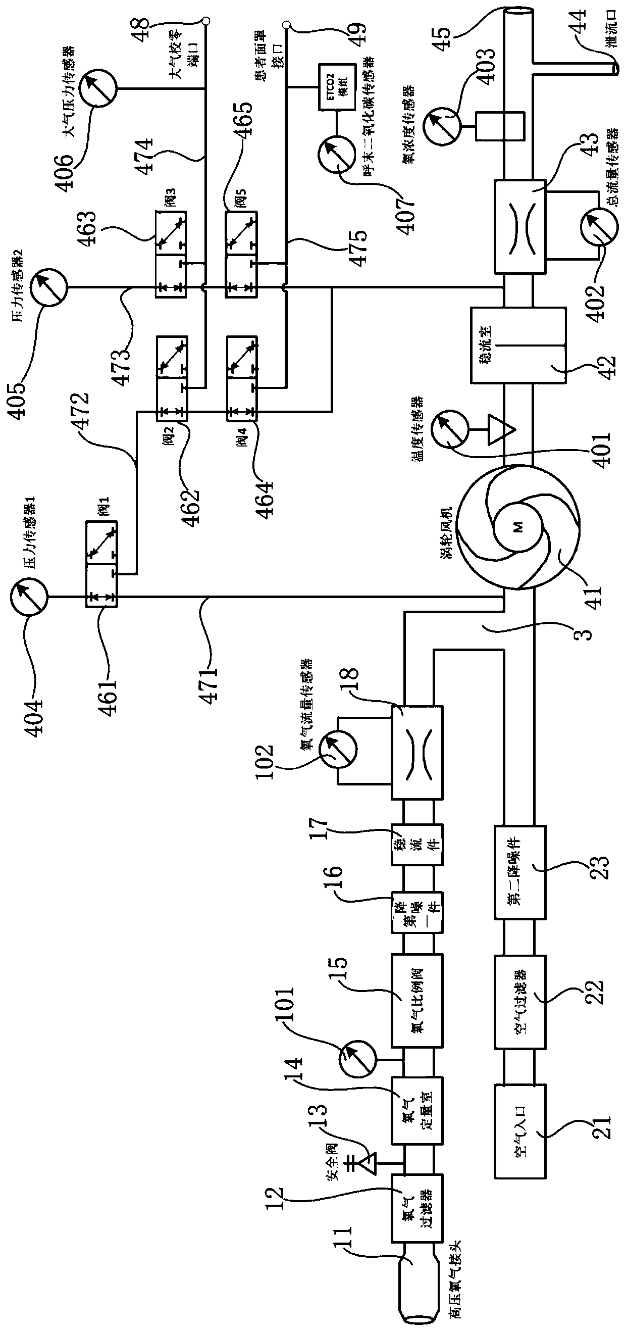
[0005] First, the ventilator is usually equipped with an air flow sensor in the air channel, and an oxygen flow sensor in the oxygen channel, so as to monitor the flow of the air channel and the oxygen channel respectively, and after the air and oxygen are mixed There is no flow monitoring at the rear end of the fan, no matter what kind of oxygen concentration the mixed gas is transmitted to the patient connection port through the airway, the total flow will inevitably have a certain loss, so the traditional way is to add the air flow and oxygen flow The way to get the total flow, the obtained total flow data is not accurate;
[0006] Second, traditional ventilators usually do not have an oxygen concentration detection function. The oxygen concentration control is obtained by calculating the volume parameter of the mixed flow of air and oxygen, and the oxygen concentration data obtained in this way is not accurate. In the ventilator equipment It is difficult to achieve high-precision control of oxygen concentration when the oxygen concentration cannot be determined;
[0007] Third, end-tidal carbon dioxide (ETCO 2 ) monitoring can reflect pulmonary ventilation and pulmonary blood flow. When mechanically ventilated patients experience failures such as air leakage, catheter twisting, and tracheal obstruction, ETCO can occur immediately. 2 Changes in numbers and shapes and alarms, while timely detection and corresponding processing, the existing ventilator does not have the function of carbon dioxide detection at one end of the breathing mask, end-tidal carbon dioxide (ETCO 2 ) When clinicians need to obtain the end-tidal carbon dioxide monitoring value of the patient, they often need to use an additional end-tidal carbon dioxide monitor, which is troublesome to use, increases the cost of equipment, and the labor of doctors or nurses;
[0008] Fourth, the ventilator pressurizes the air through the fan to provide an air flow with a certain pressure or flow rate, but in the existing ventilator, there is no negative pressure monitoring on the fan inlet end, because the air flow at the fan inlet end The inlet pressure affects the working efficiency of the fan. If the resistance of the fan inlet is too large, the temperature of the fan output airflow will increase, which will increase the temperature of the gas input to the patient, causing discomfort to the patient. The resistance of the fan inlet is too large. It will reduce the pressure and flow of the fan output gas, reduce the control accuracy of the ventilator, and seriously affect the treatment effect of the patient;
[0009] Fifth, the ventilator is an important medical device used to prevent and treat breathing disorders, save or even prolong the life of patients, and its normal and effective operation is an important guarantee for the safety of patients' lives. Therefore, it is more important to monitor the flow and pressure in the airway of the ventilator. It is very important that the existing alarm monitoring device of the ventilator simply detects the airflow pressure value in the airway by setting the pressure sensor. Once the pressure sensor fails, it cannot really realize the effective supervision of the patient's respiratory airflow; and, Measuring airway pressure alone does not enable true fault detection

Method used


Image

  • Breathing support device
  • Breathing support device
  • Breathing support device

Examples


Embodiment Construction

[0043] The following will clearly and completely describe the technical solutions in the embodiments of the present invention with reference to the accompanying drawings in the embodiments of the present invention. Obviously, the described embodiments are only part of the embodiments of the present invention, not all of them. Based on the embodiments of the present invention, all other embodiments obtained by persons of ordinary skill in the art without creative efforts fall within the protection scope of the present invention.

[0044] It should be noted that all directional indications (such as up, down, left, right, front, back...) in the embodiments of the present invention are only used to explain the relationship between the components in a certain posture (as shown in the accompanying drawings). Relative positional relationship, movement conditions, etc., if the specific posture changes, the directional indication will also change accordingly.

[0045] In addition, in t...


PUM


Abstract

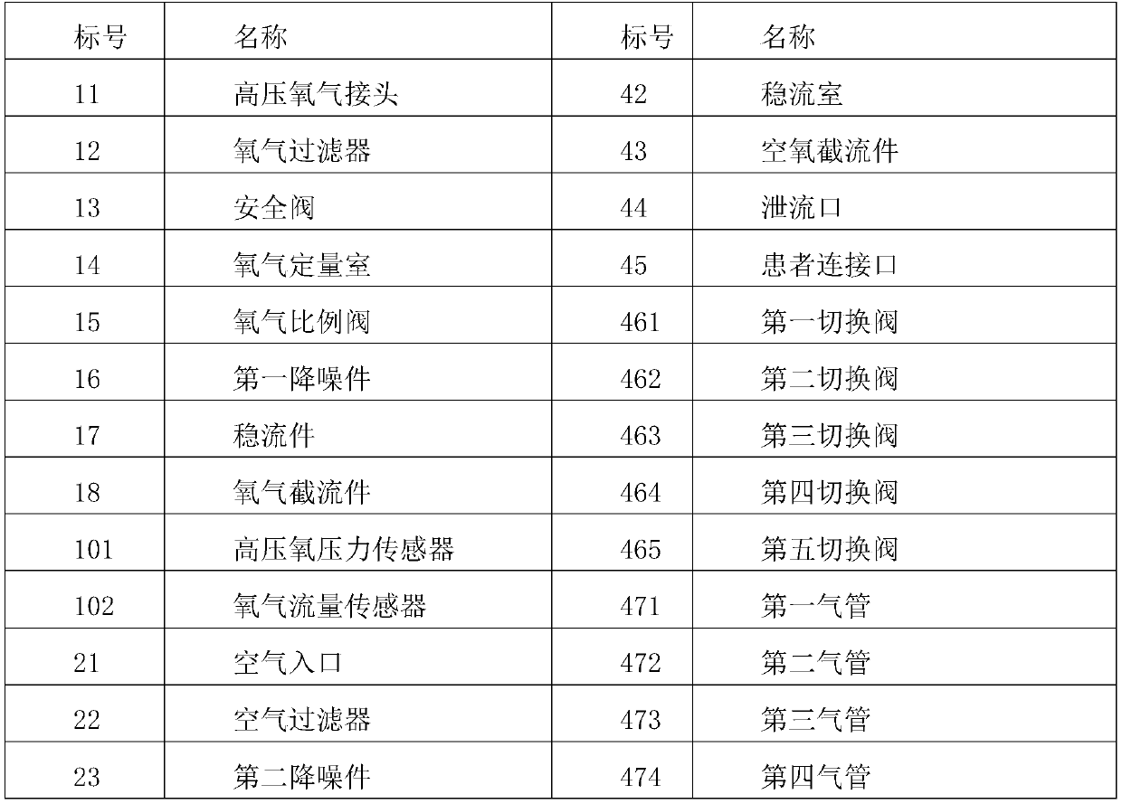
The invention discloses a breathing support device. The device comprises an oxygen gas circuit, an air gas circuit and an air-oxygen mixing chamber, the air inlet end of the oxygen gas circuit is connected to a hyperbaric oxygen source, the air inlet end of the air gas circuit is connected to an air source, the air inlet end of the air-oxygen mixing chamber is connected to the air outlet ends of the oxygen gas circuit and the air gas circuit, and the air outlet end of the air-oxygen mixing chamber is connected to a patient connecting port; and an air-oxygen mixing gas channel is arranged between the air-oxygen mixing chamber and the patient connecting port, the air-oxygen mixing gas channel comprises a turbofan, a steady flow chamber and an air-oxygen closure member which are sequentiallyconnected, the air outlet of the steady flow chamber is connected to a first pressure sensor for detecting the air flow pressure of an air outlet of the steady flow chamber, total flow sensors are arranged at the front end and the rear end of the air-oxygen closure member, and an oxygen concentration sensor is arranged at the rear end of the air-oxygen closure member. The device is provided with the total flow sensors for detecting the total flow of the air-oxygen mixed airflow behind the turbofan, and is provided with the oxygen concentration sensor for detecting the oxygen concentration of the air-oxygen mixed airflow, wherein the measured value is more direct and more accurate.

Description

technical field [0001] The invention belongs to the technical field of medical equipment, and in particular relates to a respiratory support equipment. Background technique [0002] A variety of respiratory diseases and patients with clinical hypoxia need to be treated with a ventilator and supplemented with oxygen therapy to correct hypoxia, increase arterial oxygen partial pressure and oxygen saturation levels, and promote metabolism. The ventilator delivers oxygen-enriched pressurized flow to the patient's airway according to the treatment plan, which is the most direct and effective way to solve the oxygen uptake of these patients. [0003] In the patent document with the application number 201610462324.6, an air-oxygen mixed airway for a ventilator, a ventilator and a method are proposed. Air-oxygen mixing chamber, oxygen micro-proportional valve, oxygen flow sensor and oxygen shut-off piece are installed on the oxygen gas line, fan, air pressure regulating valve, air ...

Claims


Application Information

Patent Timeline
Patent Type & Authority Applications(China)
IPC IPC(8): A61M16/12A61M16/08A61M16/00A61M16/10
Inventor 戴征李伟利
Owner HUNAN MICOME ZHONGJIN MEDICAL SCI & TECH DEV CO LTD
Why Eureka
Eureka Blog
Learn More