
Stepless speed regulating energy-saving hydraulic system for cleaning sweeper truck

A technology of stepless speed regulation and hydraulic system, applied in the direction of road cleaning, cleaning methods, fluid pressure actuating devices, etc., can solve the problems of system temperature rise, high overflow pressure, system energy consumption, etc., to achieve outstanding substantive features, Convenient for overvoltage protection and low energy loss

Inactive Publication Date: 2019-05-03
GUANGDONG ESUN HEAVY IND CO LTD
View PDF7 Cites 3 Cited by
  • Summary
  • Abstract
  • Description
  • Claims
  • Application Information

AI Technical Summary

Problems solved by technology

During the sweeping process of the sweeping car, the vehicle keeps moving, and the sweeping speed can only be adjusted according to the pre-set high-speed or low-speed two-speed, and the best sweeping effect cannot be obtained; and when the sweeping speed is at the set When running at a constant speed, the excess oil at the outlet of the hydraulic pump will overflow from the relief valve. Since the overflow pressure set by the relief valve is high, the overflow will cause serious energy consumption in the system, and the excess energy will be converted into heat energy, resulting in The temperature of the system rises, which will easily affect the reliability of the system operation
[0004] As mentioned above, the actual road pollution levels of different road sections are different, and the optimal sweeping speeds required are also different. Traditional sweeping vehicles cannot adjust the optimal sweeping speed according to different road conditions to obtain the best sweeping speed. effect; and the traditional washing machine consumes a lot of energy

Method used


Image

  • Stepless speed regulating energy-saving hydraulic system for cleaning sweeper truck
  • Stepless speed regulating energy-saving hydraulic system for cleaning sweeper truck

Examples


Embodiment Construction

[0017] The features of the present invention and other relevant features are described in further detail below through the embodiments, so as to facilitate the understanding of those skilled in the art:

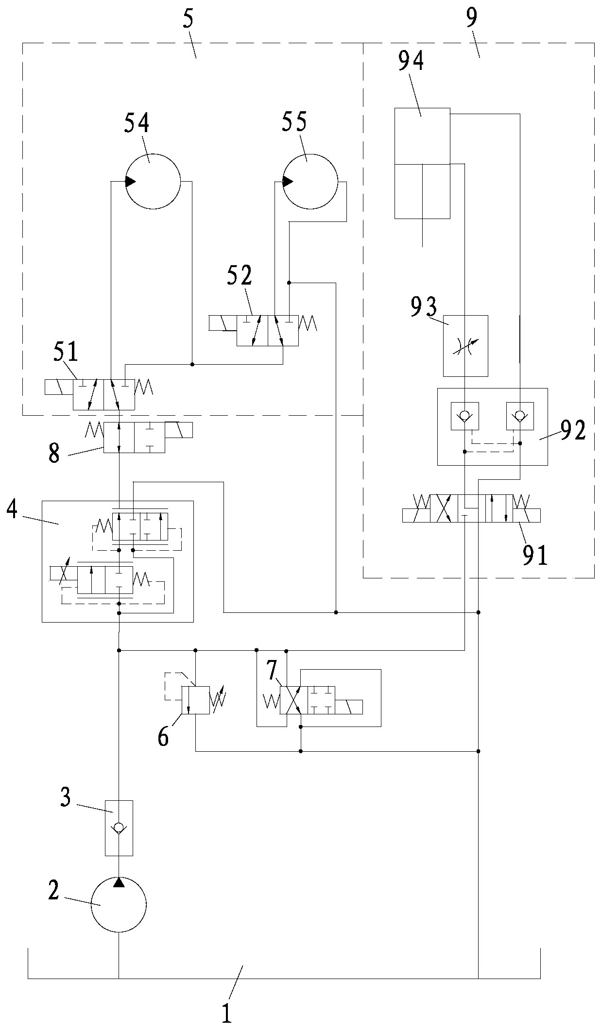
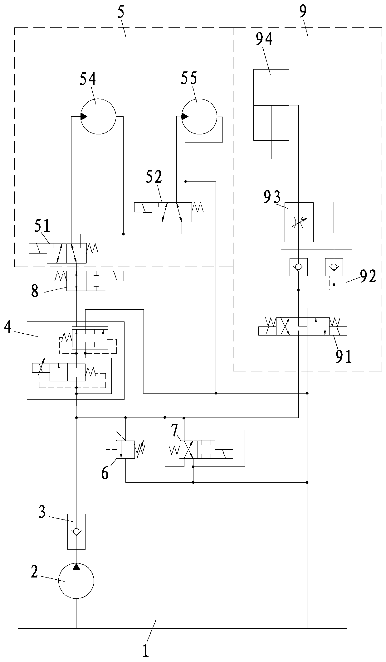
[0018] Such as figure 1 As shown, a stepless speed regulation energy-saving hydraulic system of a washing and sweeping vehicle includes a hydraulic oil tank 1, an oil pump 2, a one-way valve 3, a proportional flow control valve 4, and a hydraulic motor unit 5 for driving the sweeping plate of the washing and sweeping vehicle to rotate , an overflow valve 6, an unloading valve 7, an on-off control solenoid valve 8, and a hydraulic cylinder unit 9 for driving the sweeping swing, the proportional flow control valve 4 is provided with an oil inlet, a flow control oil outlet, And the bypass oil drain port, wherein, the hydraulic oil tank 1, the oil pump 2, the one-way valve 3, the oil inlet port and the flow control oil outlet port of the proportional flow control valve 4, the on-...


PUM


Abstract

The invention discloses a stepless speed regulating energy-saving hydraulic system for a cleaning sweeper truck. A proportional flow control valve is disposed on a pipeline before a hydraulic motor unit. The proportional flow control valve is provided with an oil inlet, a flow control oil outlet, and a bypass oil leaking opening. The invention is advantageous in that through controlling the proportional flow output at the flow control oil outlet on the proportional flow control valve, the rotating speed of the hydraulic motor unit can be controlled, so that the stepless speed regulating control can be realized; in use, a user can adjust the optimized sweeping speed based on the road pollution degree of different road segments, and the best sweeping effect can be achieved; the excessive oilcan be returned from the bypass oil leaking opening of the proportional flow control valve to a hydraulic oil tank, so that energy saving of the system can be realized; energy consumption loss is little, heating is small, and substantive features and notable progress are provided; a hydraulic cylinder unit is connected between an outlet end of a one-way valve and an oil-returning mouth of the hydraulic oil tank, which is convenient to drive the sweeping discs of the cleaning sweeper truck to rotate.

Description

technical field [0001] The invention relates to a stepless speed regulation and energy-saving hydraulic system for a washing and sweeping vehicle. Background technique [0002] Sweeper is a vehicle used for road cleaning. The speed of sweeping depends on the degree of road pollution and the particle size and density of garbage. The more serious the road pollution and the greater the particle size and density of garbage, the required sweeping speed The larger the brush speed is, the greater the speed of the brush will cause excessive dust. Therefore, to get the best sweeping effect, the speed of the brush needs to be adjusted according to the road conditions. [0003] At present, in the existing market, the high and low gear speed control valves are mostly connected in parallel, and the high speed gear speed control valve or the low speed gear speed control valve is selected according to the reversing valve to drive the brush by oil supply, so as to realize the high and low s...

Claims


Application Information

Patent Timeline
IPC IPC(8): E01H1/00E01H1/05F15B11/08F15B13/02
Inventor 倪振中李葳彭稳
Owner GUANGDONG ESUN HEAVY IND CO LTD
Learn More