
Reforming hydrogen production reactor, reforming hydrogen production conversion furnace, and reforming hydrogen production reaction method

A reforming hydrogen production and reactor technology, applied in chemical instruments and methods, hydrogen, inorganic chemistry, etc., can solve the problems of increasing the energy consumption of the raw gas compressor, increasing the number of catalyst active centers, and the catalyst being prone to carbon deposition and deactivation. , to achieve the effect of total reduction, long service life, and not easy carbon deposition and inactivation

Active Publication Date: 2019-04-30
SINOPEC ENG +1
View PDF5 Cites 1 Cited by
  • Summary
  • Abstract
  • Description
  • Claims
  • Application Information

AI Technical Summary

Problems solved by technology

[0008] The existing hydrogen production conversion furnace is filled with a nickel-based catalyst of a certain particle size and shape in the furnace tube, which often causes uneven loading, causing the raw material gas to drift, resulting in a low conversion rate of the raw material, and the catalyst is prone to carbon deposition and deactivation. operating cycle
In addition, the catalyst with smaller particle size is loaded in the furnace tube, although it can increase the loading amount of the catalyst, increase the number of catalyst active centers, and improve the processing capacity and conversion rate of raw materials to a certain extent, the disadvantage is that the smaller the catalyst size, the furnace The larger the pipe pressure drop, the higher the energy consumption of the feed gas compressor

Method used


Image

  • Reforming hydrogen production reactor, reforming hydrogen production conversion furnace, and reforming hydrogen production reaction method
  • Reforming hydrogen production reactor, reforming hydrogen production conversion furnace, and reforming hydrogen production reaction method
  • Reforming hydrogen production reactor, reforming hydrogen production conversion furnace, and reforming hydrogen production reaction method

Examples


Embodiment 1

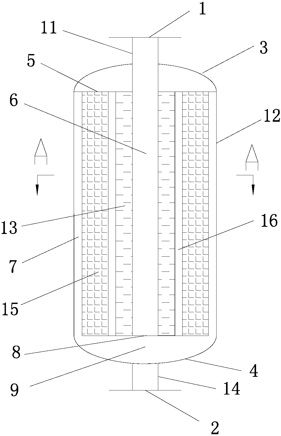
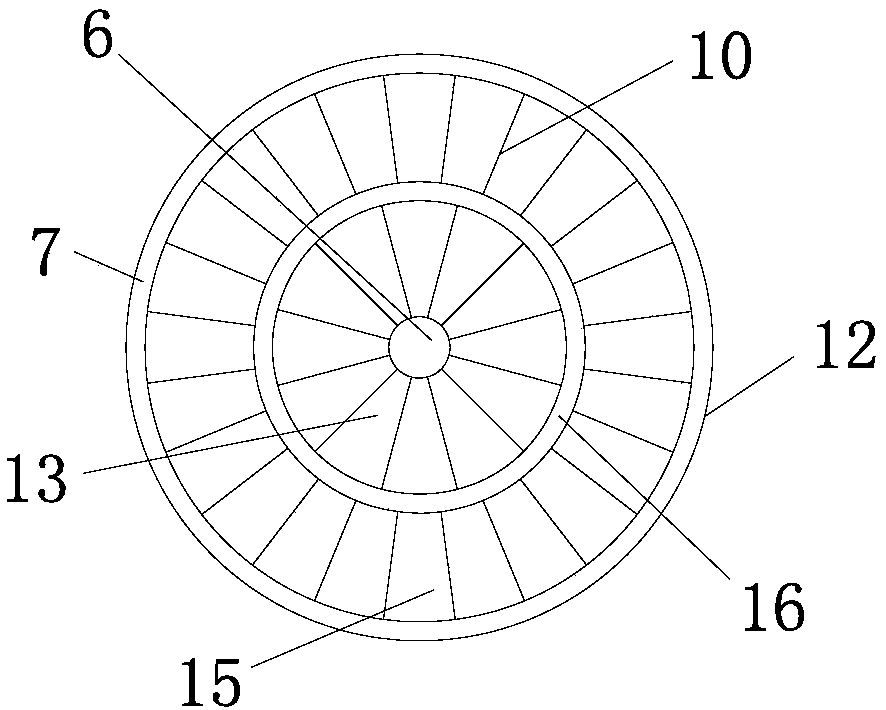
[0083] Such as figure 1 , figure 2 As shown, the reforming hydrogen production reactor used in this embodiment includes a pressure-bearing shell 12 with a first straight pipe 11 at the upper end and a second straight pipe 14 at the lower end, and four sleeves 15 are arranged inside the shell. (not all shown in the figure) and a radial catalytic reaction zone formed by a central cylinder 13, the upper part of the first straight pipe 11 is provided with an air inlet 1, and the lower part of the second straight pipe 14 is provided with an air outlet 2. The catalytic reaction zone is composed of a flat micro-catalytic reaction plate 10, the angle between the micro-catalytic reaction plate 10 and the horizontal direction is 90°, and the micro-catalytic reaction plates 10 are radially and evenly distributed around the central tube or the central tube respectively, the central tube 6, the central tube 13 , the sleeve 15 and the housing 12 are coaxially arranged; the micro-catalysis...

Embodiment 2

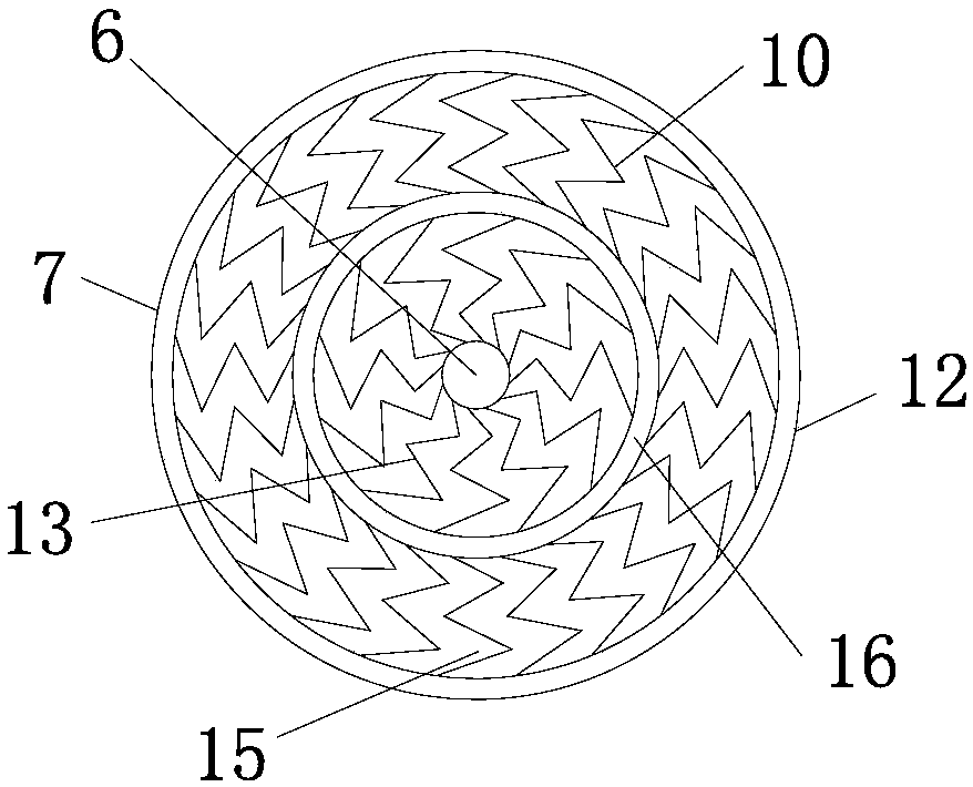
[0094] Such as figure 1 , image 3 , Figure 9 As shown, the reforming hydrogen production reactor and the reforming furnace of the present embodiment are the same as the reactor size of Example 1, the distance between two adjacent micro-catalysis reaction plates, the distance between the ring gaps, the matrix material and the active group per unit area of ​​the micro-catalysis reaction plates The NiO loading parameters are the same. The difference from Example 1 is that the micro-catalytic reaction plate in this example is a toothed micro-reaction plate, and the wave direction is along the axial direction of the reactor. For the toothed plate, the distance between the crest and the trough is 4mm, and the distance between two adjacent crests or adjacent troughs of the same microplate is 6.5mm. The reforming hydrogen production reactor and reformer of this embodiment are applied to the hydrogen production reaction by steam reforming of natural gas. The hydrogen production p...

Embodiment 3

[0099] Such as figure 1 , Figure 4 , Figure 11 As shown, the reforming hydrogen production reactor and the reforming furnace of the present embodiment are the same as the reactor size of Example 1, the distance between two adjacent micro-catalysis reaction plates, the distance between the ring gaps, the matrix material and the active group per unit area of ​​the micro-catalysis reaction plates The NiO loading parameters are the same. The difference from Example 1 is that the micro-catalytic reaction plate in this example is a corrugated micro-reaction plate, and the wave direction is along the axial direction of the reactor. For the corrugated plate, the distance between the crest and the trough is 4mm, and the distance between two adjacent crests or adjacent troughs of the same micro-catalytic reaction plate is 6.5mm.

[0100] The reforming hydrogen production reactor and reformer of this embodiment are applied to the hydrogen production reaction by steam reforming of na...


PUM


Abstract

The present invention relates to a reforming hydrogen production reactor, a reforming hydrogen production conversion furnace, and a reforming hydrogen production reaction method. According to the present invention, the reforming hydrogen production reactor and the reforming hydrogen production conversion furnace adopt a micro-catalytic reaction plate, wherein a catalytic active component is loadedon the reaction plate, such that the consumption of catalytic active metals is reduced, the catalyst is not easily subjected to carbon deposition deactivation, the diffusion distance of the reactiongas to the catalytic active center is shortened, the mass transfer resistance and the pressure drop of the reactor are reduced, and the conversion rate of the hydrogen production reaction is increased; the reaction gas flows outward from the center in the reactor, the flow channel area is gradually increased, and the temperature of the reaction plate is gradually increased, such that the conversion rate of the hydrogen production reaction as volume increase and endothermic reaction is easily increased; the reactor has wide use range, and the furnace tube as the hydrogen production conversion furnace can be used for different types of conversion furnaces; and the hydrogen production method using the reforming hydrogen production conversion furnace has the reduced furnace tube pressure drop,the space-time yield of the product per unit volume of the catalyst in the furnace tube is high, the conversion rate of the raw material gas processing capacity is high, and the requirements of the hydrogen production reaction can be met.

Description

technical field [0001] The present disclosure relates to the field of reforming hydrogen production, and in particular, to a reforming hydrogen production reactor, a reforming hydrogen production conversion furnace and a method for reforming hydrogen production reaction. Background technique [0002] Hydrogen is not only an important chemical raw material, but also a clean fuel. Hydrogen plays an increasingly important role in modern industry, especially petrochemical industry, fuel cell and other national economies. Under the multiple pressures of increasing crude oil quality and inferior quality in the world, increasing demand for clean oil products, continuously improving quality standards, and increasingly stringent environmental regulations, the demand for hydrogen is also increasing, and the demand for hydrogen production is also increasing. Devices also put forward higher requirements. [0003] Hydrogen production processes mainly include water electrolysis, light h...

Claims


Application Information

Patent Timeline
IPC IPC(8): C01B3/32C01B3/38
CPCC01B3/32C01B3/38C01B2203/0227C01B2203/0233C01B2203/1041C01B2203/1058C01B2203/1241C01B2203/141Y02P20/52
Inventor 张旭戴文松蒋荣兴
Owner SINOPEC ENG
Learn More