Carbon fiber composite material and aluminum material indirect induction heating rivetless joint vibration joint mold and process

A technology of induction heating and carbon fiber, which is applied in the field of stamping connection, can solve the problems that the connection method is difficult to realize, and the anisotropic composite material cannot be fully utilized, so as to reduce heat loss, avoid low heating efficiency, and enhance the connection strength.

Active Publication Date: 2020-03-17
唐山格诺金属科技有限公司
View PDF3 Cites 0 Cited by
  • Summary
  • Abstract
  • Description
  • Claims
  • Application Information

AI Technical Summary

Problems solved by technology

However, the traditional stamping connection technology is widely used in the field of metal sheet connection such as steel, aluminum (aluminum alloy) and other coated non-ferrous metals, and the application between metal and composite materials, composite materials and composite materials is not relatively complete and mature. The open theoretical system of stamping connection technology, and the traditional stamping connection method is used for the connection of dissimilar composite materials, which cannot fully play its role for anisotropic composite materials, and the connection method is difficult to realize

Method used


Image

  • Carbon fiber composite material and aluminum material indirect induction heating rivetless joint vibration joint mold and process
  • Carbon fiber composite material and aluminum material indirect induction heating rivetless joint vibration joint mold and process
  • Carbon fiber composite material and aluminum material indirect induction heating rivetless joint vibration joint mold and process

Examples


Embodiment Construction

[0026] In order to make the purpose, technical solutions and advantages of the embodiments of the present invention clearer, the technical solutions in the embodiments of the present invention will be clearly and completely described below in conjunction with the drawings in the embodiments of the present invention. Obviously, the described embodiments It is a part of embodiments of the present invention, but not all embodiments.

[0027] In describing the present invention, it is to be understood that the terms "radial", "axial", "upper", "lower", "top", "bottom", "inner", "outer" etc. indicate orientation Or the positional relationship is based on the orientation or positional relationship shown in the drawings, which is only for the convenience of describing the present invention and simplifying the description, and does not indicate or imply that the referred device or element must have a specific orientation, be constructed and operated in a specific orientation , and the...


PUM


Abstract

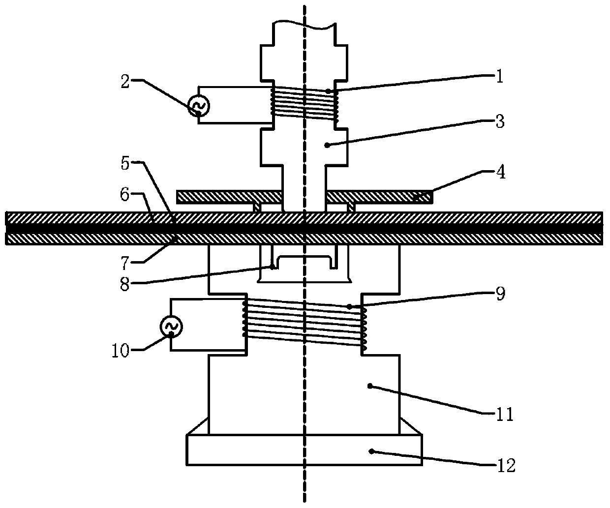
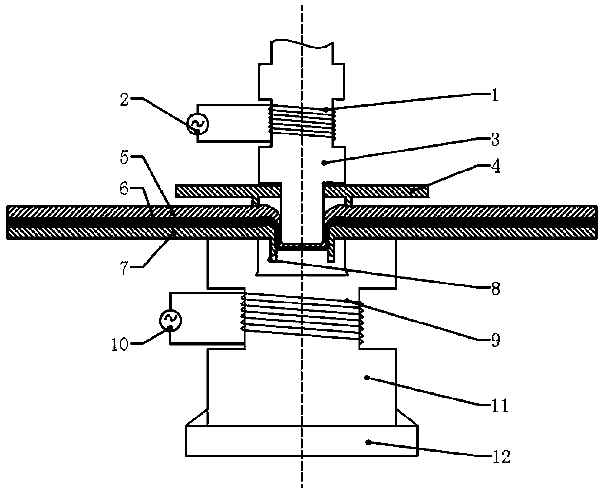
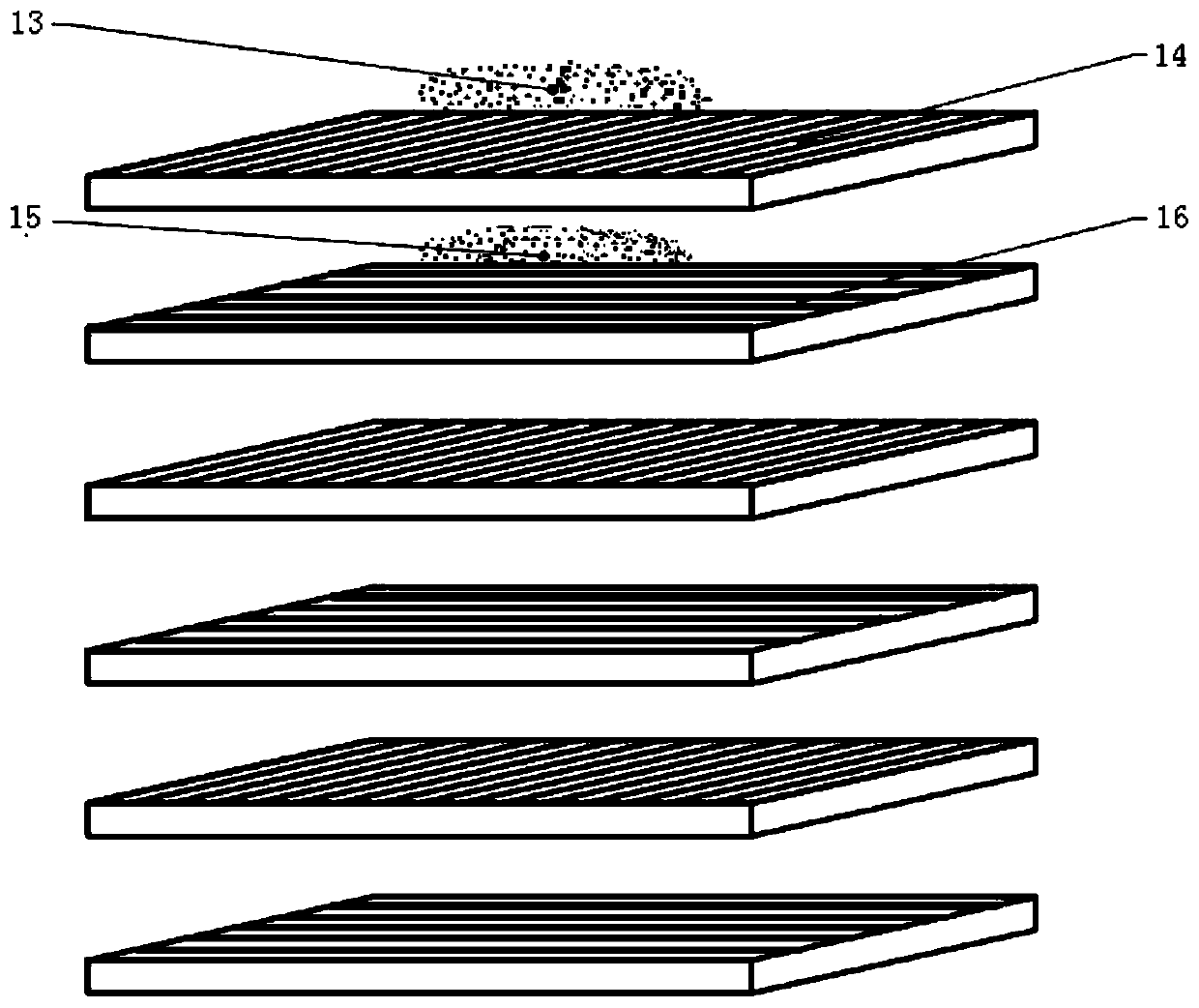
The invention provides a rivetless connection vibration joint die and technology heated through indirect induction of carbon fiber composite materials and aluminum alloy materials. Connecting parts composed of carbon fiber composite boards, sandwich structures and aluminum alloy sheets are placed on a lower die and the upper surface of a concave die, the connecting parts are fixed through blank holders, the concave die and an upper die punch are risenat thetemperature and heated through a lower die electromagnetic induction coil and an upper die electromagnetic induction coil correspondingly,and the connecting parts are subjected to local temperature control. An ultrasonic high-frequency vibrator is turned on, the upper die punch moves downwards to extrude the connecting parts, and plastic deformation is achieved on the aluminum alloy sheets and the carbon fiber composite boards under the action of stamping force and ultrasonic oscillation. Meanwhile, due to extrusion of the upper diepunch and the concave die and the oscillating action of ultrasonic wave, resin in the sandwich structuresand carbon fibers are rearranged, and aluminum powder and the resin are embedded in the sheetsin a coated mode. A curing reaction of the resin occurs, finally, the aluminum alloy sheets, the sandwich structures and the carbon fiber composite boards are mutually connected in a hooked mode andembedded, and the aluminum alloy sheets and the carbon fiber composite boards are mutually connected.

Description

technical field [0001] The invention relates to the field of stamping connection, in particular to an indirect induction heating rivetless connection vibration joining mold and technology of carbon fiber composite materials and aluminum materials. Background technique [0002] With the rapid development of the automobile industry, the application of automobile lightweight technology is the general trend. Lightweight alternative materials are generally recognized as the most valuable lightweight technology in the industry. Aluminum alloys have been widely used in car bodies, and new materials such as non-metal fiber composite materials are gradually being used in car body manufacturing. For non-metallic fiber composite materials, if the traditional method is used to connect two sheets together, then the cost of a single connection is relatively high. Existing mature technologies such as riveted or bolted joints require high preparation work, transportation costs, and process...

Claims


Application Information

Patent Timeline
Patent Type & Authority Patents(China)
IPC IPC(8): B29C70/68B29C70/78B29C33/00B29C33/02
CPCB29C33/00B29C33/02B29C70/681B29C70/78
Inventor 王健于跃李佳腾张广武付昌云郑学丰
Owner 唐山格诺金属科技有限公司
Why Eureka
Try Eureka