Mechanical interlocking device of circuit breaker and circuit breaker device

A technology of mechanical interlocking and circuit breakers, applied in emergency protection devices, circuits, parts of protection switches, etc., can solve problems such as failure of pressing force, unreliable pressing force, and easy conduction of metal parts.

Pending Publication Date: 2022-02-18
CHINT LOW VOLTAGE ELECTRICAL TECH CO LTD
View PDF0 Cites 0 Cited by
  • Summary
  • Abstract
  • Description
  • Claims
  • Application Information

AI Technical Summary

Problems solved by technology

When the power distribution system is running, only one of them can be used for power supply. If two channels supply power at the same time, it will cause abnormal voltage of electrical equipment and grid, seriously affect equipment operation and grid safety, and cause power accidents. Therefore, mechanical interlock or electrical The way of interlocking to ensure that only one of the two power supplies is input
[0003] The existing mechanical interlocking device is usually pressed vertically on the circuit breaker of one of the power sources to prevent the operating handle from closing, but this pressing force is unreliable, and if it is slightly loose, the pressing force will fail
[0004] In addition, the existing mechanical interlocking devices for circuit breakers are usually installed on the TH35-7.5 mounting rail or on the side of the circuit breaker, and the user has the problem of inconvenient installation and unstable installation during the installation process
[0005] In addition, the existing mechanical interlocking devices are usually made of sheet metal parts. During the process of operating the operating handle of the circuit breaker to open and close, the hands are easily scratched by the burrs on the fractured surface of the sheet metal parts, and the metal parts are easy to conduct electricity. There is an electrical hazard

Method used


Image

  • Mechanical interlocking device of circuit breaker and circuit breaker device
  • Mechanical interlocking device of circuit breaker and circuit breaker device
  • Mechanical interlocking device of circuit breaker and circuit breaker device

Examples


Embodiment Construction

[0035] Contraction below Figure 1 to 11 The embodiment given further illustrates a specific embodiment of a mechanical interlocking apparatus of the circuit breaker created by the present invention. The mechanical interlocking apparatus of the circuit breaker created by the present invention is not limited to the description of the following embodiments.

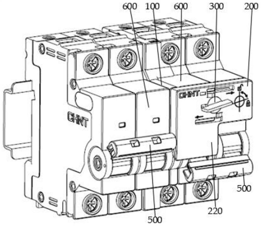
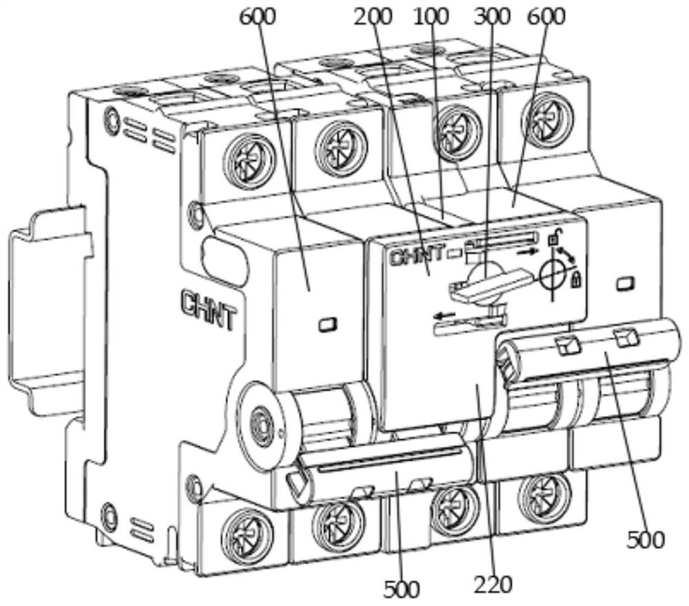
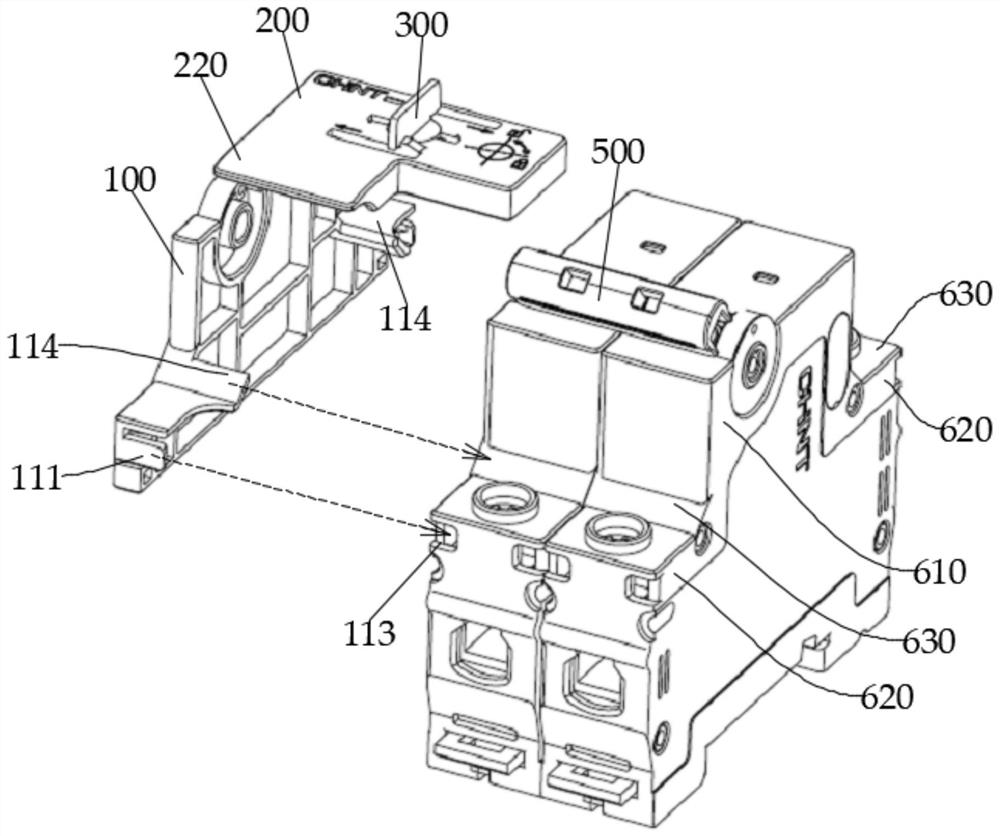
[0036] like Figure 1-5 As shown, the mechanical interlocking device of the circuit breaker is used to implement the mechanical interlock of the two sets of circuit breakers, including the outer casing 100 and the slider 200 that can be moved on the outer casing 100, characterized in that the slider 200 is provided. The rotation knob 300, the knob 300 drives the slide 200 to move to the circuit breaker handle 500 in which any of the set of circuit breakers is moved to the closing position, and avoid the circuit breaker handle 500 of another set of circuit breakers. At this time, the knob 300 can rotate. To the housing 100, the sl...


PUM


Abstract

The invention discloses a mechanical interlocking device of a circuit breaker and a circuit breaker device. The mechanical interlocking device is fixedly mounted between the side surfaces of two groups of circuit breakers of the circuit breaker device, is used for realizing mechanical interlocking of the two groups of circuit breakers, and comprises a shell and a sliding cover movably arranged on the shell, and a rotatable knob is arranged on the sliding cover; the knob drives the sliding cover to move so as to prevent the circuit breaker handle of any group of circuit breakers from moving to the closing position and avoid the circuit breaker handle of the other group of circuit breakers; at the moment, the knob can rotate to be locked and limited with the shell to prevent the sliding cover from moving.

Description

Technical field [0001] The present invention has created a mechanical interlocking apparatus and a circuit breaker device according to a low-voltage electrical field, particularly a circuit breaker. Background technique [0002] In low-voltage power distribution systems, many important power supply sites will use two power supply, all the way to the main power supply, all the way for a spare power. The power supply system can only be used in operation. If the two simultaneous power supply, it will cause an electrical equipment and grid voltage abnormality, seriously affect the equipment operation and power grid safety, resulting in electricity accidents, so there must be mechanically interlocking or electrical Interlocking way to ensure that only one power input is all previously used. [0003] The existing mechanical interlocking device is typically vertically pressed against a circuit breaker in which a power source is pulled to block the operating handle, but this pressure is ...

Claims


Application Information

Patent Timeline
IPC IPC(8): H01H71/02H01H71/10H01H71/50H01H9/26
CPCH01H71/02H01H71/1009H01H71/505H01H9/26
Inventor 葛伟骏
Owner CHINT LOW VOLTAGE ELECTRICAL TECH CO LTD
Why Eureka
Try Eureka