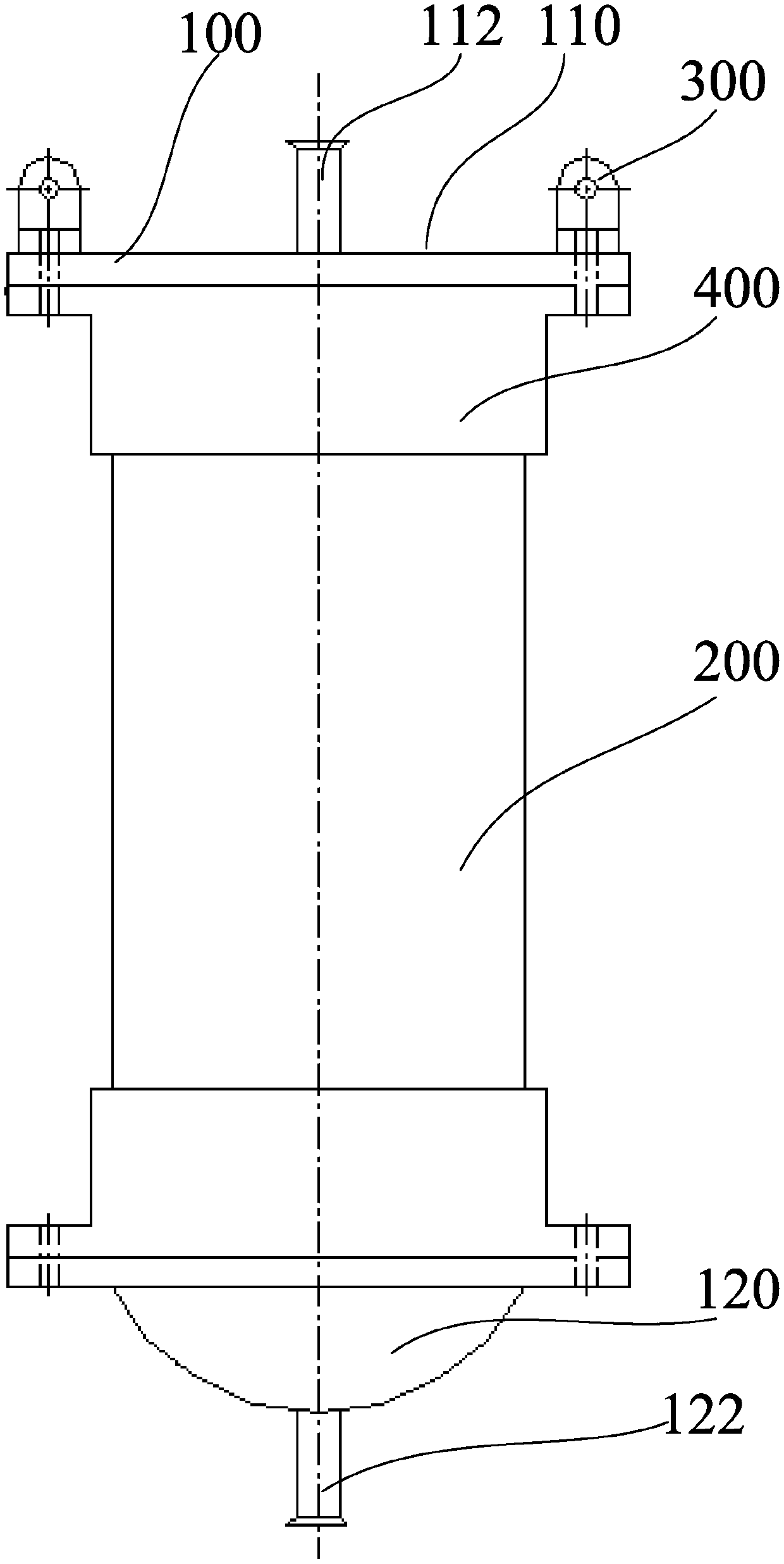
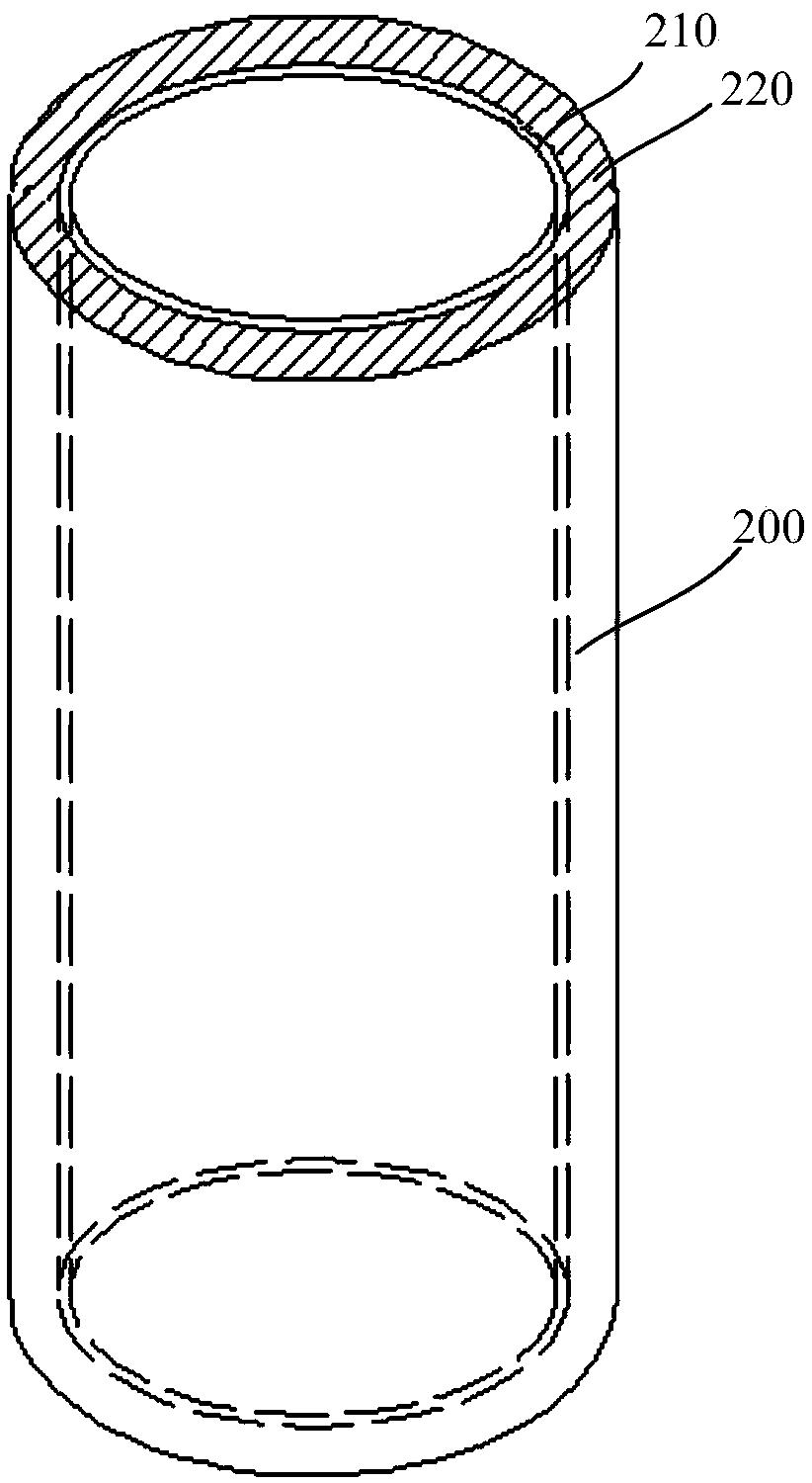
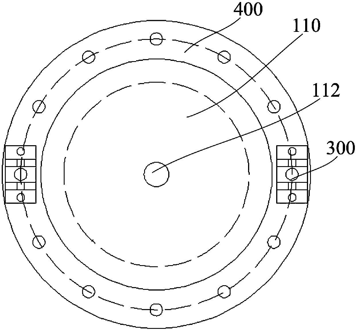
Anti-ionizing radiation container and preparation method thereof
A technology of ionizing radiation and containers, applied in the field of nuclear power, can solve problems such as performance degradation, metal materials are easily corroded, and cannot meet the requirements
- Summary
- Abstract
- Description
- Claims
- Application Information
AI Technical Summary
Problems solved by technology
Method used
Image
Examples
preparation example Construction
[0062] The embodiment of the present invention also provides a preparation method of the anti-ionizing radiation container, comprising:
[0063] S10, providing the solution of the resin system and the inner lining layer 210;
[0064] S20, loading the solution of the resin system on the fiber and the metal wire;
[0065] S30, winding the fiber loaded with the resin system solution and the metal wire on the outer surface of the inner liner 210 to form a preformed container body 200;
[0066] S40, performing curing treatment on the preformed container body 200 to form the container body 200; and
[0067] S50, assembling the container body 200 and the end cap 100.
[0068] In step S10, the solution of the resin system includes the resin system and a solvent, and the solvent may be an organic solvent such as ethanol, toluene, acetone, ethyl acetate, etc., preferably a highly volatile organic solvent. The solvent can be determined according to the type of the resin.
[0069] In ...
Embodiment 1
[0085] (1) Material preparation: 100 parts by weight of tetraglycidylamine epoxy resin (AG80) and 58 parts by weight of diaminodiphenylsulfone (DDS) curing agent were weighed. The curing agent is dissolved by adding a small amount of acetone, and the acetone solution of the dissolved curing agent is mixed with the tetraglycidylamine epoxy resin until the solution is uniform and clear to obtain a mixed solution of the resin and the curing agent. Take by weighing 16 parts by weight of micron-sized erbium oxide (Er 2 o 3 ) shielding filler (particle size 5-7μm), 15 parts by weight of acetone and 5 parts by weight of KH560 silane coupling agent, KH560 silane coupling agent is dissolved in acetone, then add erbium oxide shielding filler, at a temperature of 10 ° C ~ Stir evenly at 40°C and activate at a constant temperature to prepare a modified shielding filler solution. Mix the modified barrier filler solution with the mixed solution of resin and curing agent, and adjust the so...
Embodiment 2
[0093] The same as the steps of steps (1)-(2), (4)-(7) of Example 1, the difference is that step (3) is:
[0094] (3-1) Winding of the fiber layer 222: Make the fiber pass through the dipping tank 510 and the ultrasonic device 520 filled with the solution of the resin system prepared in step (1) at a certain pulling speed. The fiber bundles of pre-impregnated fibers are paralleled at the winding nozzle 540 after passing through the tension roller 530, and are wound on the alloy lining layer 210 according to the combination of spiral winding and hoop winding, and are wound layer by layer to the designed number of layers , to obtain the fiber layer 222 .
[0095] (3-2) Tungsten wire layer winding: passing through the dipping tank 510 and the ultrasonic device 520 filled with the solution of the resin system prepared in step (1). The fiber bundle of the prepreg tungsten wire passes through the tension roller 530 and is paralleled at the wire winding nozzle, and is wound on the a...
PUM
| Property | Measurement | Unit |
|---|---|---|
| Diameter | aaaaa | aaaaa |
| Diameter | aaaaa | aaaaa |
| Diameter | aaaaa | aaaaa |
Abstract
Description
Claims
Application Information
 - R&D
- Intellectual Property
- Life Sciences
- Materials
- Tech Scout
- Unparalleled Data Quality
- Higher Quality Content
- 60% Fewer Hallucinations
Browse by: Latest US Patents, China's latest patents, Technical Efficacy Thesaurus, Application Domain, Technology Topic, Popular Technical Reports.
© 2025 PatSnap. All rights reserved.Legal|Privacy policy|Modern Slavery Act Transparency Statement|Sitemap|About US| Contact US: help@patsnap.com


