


Quick Research
Generate reliable direction feasibility study reports for your R&D in just a few steps.

Technical Q&A
Discover and master advanced knowledge NOW. Basics, ideas, possibilities, all at once.

Find Solutions
As an expert in R&D theories, this can generate solutions to your technical problems instantly.

Evaluate Feasibility
Analyze your overall solution with one click, know your potential R&D risks in advance.

Monitor Landscape
Get weekly tech updates, stay abreast of the latest tech innovations and key insights.
Novel graphite corrugated heat exchange plate heat exchanger
A technology of graphite heat exchange and heat exchanger, which is applied in the direction of heat exchanger types, indirect heat exchangers, heat exchange equipment, etc., can solve the problems of large thermal resistance, low heat transfer efficiency, small thermal resistance, etc., to reduce the interface Liquid film thermal resistance, not easy to deposit and block, excellent heat transfer efficiency
- Summary
- Abstract
- Description
- Claims
- Application Information
AI Technical Summary
Problems solved by technology
Method used
Image


Examples
Embodiment 1
[0032] Such as Figure 4 to Figure 6 As shown, a single-flow graphite corrugated heat exchanger includes a first cover plate 1, a first head 2, a gasket 3, a graphite heat exchange plate 4, a second head 5, and a second cover plate 6 and fasteners 7, the first cover plate 1 and the second cover plate 6 are symmetrically arranged, and a multi-layer graphite heat exchange plate 4 is stacked between the first cover plate 1 and the second cover plate 6, and the two The graphite heat exchange plate 4 at the end and the end cover plate are respectively provided with a first head 2 and a second head 5, and the graphite heat exchange plates 4 of each layer are separated by a gasket 3, and the multi-layer graphite heat exchange plate The thermal plate 4 is fixed through by fasteners 7 .
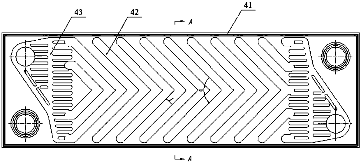
[0033] In this example, if figure 1 and figure 2 As shown, the graphite heat exchange plate 4 includes a frame 41, the frame 41 is provided with a heat exchange area 42 and a liquid distribution ...
Embodiment 2
[0041] Such as Figure 7 to Figure 9 As shown, a multi-process graphite corrugated heat exchanger includes a first cover plate 1, a first head 2, a gasket 3, a graphite heat exchange plate 4, a second head 5, and a second cover plate 6. Fasteners 7 and baffles 12, the first cover plate 1 and the second cover plate 6 are symmetrically arranged, and multi-layer graphite replacement plates are stacked between the first cover plate 1 and the second cover plate 6 The heat plate 4, the graphite heat exchange plate 4 at both ends and the end cover plate are respectively provided with a first head 2 and a second head 5, and the graphite heat exchange plates 4 of each layer are separated by a gasket 3 The middle part of the multilayer graphite heat exchange plate 4 is provided with a baffle plate 12 for baffle, and the multilayer graphite heat exchange plate 4 is penetrated and fixed by fasteners 7 .
[0042] In this example, if figure 1 and figure 2 As shown, the graphite heat ex...
PUM
 Abstract
Description
Claims
Application Information
 - R&D Engineer
- R&D Manager
- IP Professional
- Industry Leading Data Capabilities
- Powerful AI technology
- Patent DNA Extraction
Browse by: Latest US Patents, China's latest patents, Technical Efficacy Thesaurus, Application Domain, Technology Topic, Popular Technical Reports.
© 2024 PatSnap. All rights reserved.Legal|Privacy policy|Modern Slavery Act Transparency Statement|Sitemap|About US| Contact US: help@patsnap.com