Brazing plate heat exchanger and manufacturing method for heat exchanger

A technology of heat exchanger and manufacturing method, which is applied to heat exchanger fixing, heat exchange equipment, manufacturing tools, etc., can solve problems such as affecting normal use, difficulty in welding, trouble in use, etc., so as to improve production efficiency, simplify welding difficulty, Connection for reliable effects

Pending Publication Date: 2019-04-19
NINGBO HRALE PLATE HEAT EXCHANGER
View PDF0 Cites 0 Cited by
  • Summary
  • Abstract
  • Description
  • Claims
  • Application Information

AI Technical Summary

Problems solved by technology

[0002] At present, the pipe joints of heat exchangers on the market are mostly made of the same stainless steel material as the cover plate of the heat exchanger, which can facilitate the welding and forming of the heat exchanger. The liquid inlet pipe is connected, because the melting point of stainless steel and copper is different, so welding is more difficult, and cracks are likely to occur, resulting in weak welding and affecting normal use, which will bring great trouble to after-sales installation and user use. It has improved space

Method used


Image

  • Brazing plate heat exchanger and manufacturing method for heat exchanger
  • Brazing plate heat exchanger and manufacturing method for heat exchanger
  • Brazing plate heat exchanger and manufacturing method for heat exchanger

Examples


Embodiment 1

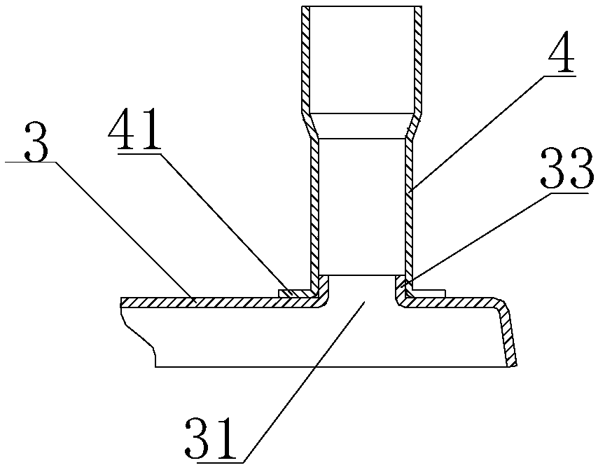
[0026] Such as figure 2 As shown, the mouth edge of the cover plate 3 corresponding to the installation port 31 is turned upwards to form a columnar flange 33 , and the lower end of the pipe joint 4 is turned outward to form a ring-shaped welding part 41 . The pipe joint 4 is sleeved on the columnar flange 33 and the welding portion 41 is pressed against the surface of the cover plate 3 , and the connection between the pipe joint 4 and the cover plate 3 is connected together by welding.

Embodiment 2

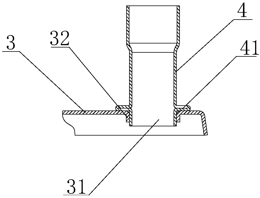
[0028] Such as image 3 As shown, the mouth edge of the cover plate 3 corresponding to the installation port 31 is folded downward to form a tubular flange 32, and the middle part of the pipe joint 4 is formed with an annular welding portion 41, which is formed by the folds of the pipe body of the pipe joint 4. Formed, the lower end of the pipe joint 4 is plugged into the tubular flange 32 and the welding portion 41 is pressed against the surface of the cover plate 3 , and the connection between the pipe joint 4 and the cover plate 3 is connected together by welding.

[0029] Manufacturing method for the above-mentioned brazed plate heat exchanger:

[0030] The manufacturing method includes two furnace feedings, one furnace feeding is used for welding the heat exchange main body and the heat exchange main body, the cover plate, and the cover plate to form a semi-finished heat exchanger; the second furnace feeding is used for the semi-finished product and the heat exchanger We...


PUM

PropertyMeasurementUnit
melting pointaaaaaaaaaa

Abstract

The invention discloses a brazing plate heat exchanger and a manufacturing method for the heat exchanger plate. The brazing plate heat exchanger includes a heat exchanger main body, a bottom plate, acover plate and a pipe joint, the pipe joint is welded to the cover plate, the heat exchanger plate, the cover plate and the bottom plate are made by punching of a stainless steel material, the pipe joint is made by punching of a copper material, and a flanging is arranged at the opening edge, surrounding a mounting opening, of the cover plate; and an annular welding part is formed in the pipe joint, the pipe joint is arranged on the flanging in a sleeving or inserted mode, and the welding part is welded to the plate face of the cover plate. The brazing plate heat exchanger is simple in structure, the copper pipe joint is adopted, the welding with a copper liquid inlet pipe is facilitated, and the difficulty of the after-sales installation is greatly simplified; and meanwhile, the copper pipe joint and the cover plate adopt the matching welding between the welding part and the flanging, the structure is more reliable and stable, and the welding is more convenient.

Description

technical field [0001] The invention relates to the technical field of heat exchange equipment, in particular to a brazed plate heat exchanger and a manufacturing method for the heat exchanger. Background technique [0002] At present, the pipe joints of heat exchangers on the market are mostly made of the same stainless steel material as the cover plate of the heat exchanger, which can facilitate the welding and forming of the heat exchanger. The liquid inlet pipe is connected, because the melting point of stainless steel and copper is different, so welding is more difficult, and cracks are likely to occur, resulting in weak welding and affecting normal use, which will bring great trouble to after-sales installation and user use. It has improved space. Contents of the invention [0003] The present invention aims to overcome the defects in the above-mentioned prior art, and provides a brazed plate heat exchanger. The fitting between the pipe joint and the cover plate th...

Claims


Application Information

Patent Timeline
Patent Type & Authority Applications(China)
IPC IPC(8): F28D9/00F28F3/08F28F9/00F28F9/26F28F21/08B23K31/02B23K35/30
CPCF28D9/00B23K31/02B23K35/302B23K35/3033F28F3/08F28F9/00F28F9/26F28F21/083F28F21/085F28F2275/06
Inventor 戴丁军卓宏强孙旭光
Owner NINGBO HRALE PLATE HEAT EXCHANGER
Why Eureka
Try Eureka