
An automatic calibration method for permanent magnet synchronous motor

A permanent magnet synchronous motor, automatic calibration technology, applied in the direction of control generator, motor generator control, control electromechanical brake, etc., can solve the difficulty of simultaneously taking into account the maximum torque current maximum torque voltage ratio calibration, the voltage is not enough to adjust the current Size, system out of control and other problems, to achieve the effect of reducing equipment dependence and calibration costs, avoiding delays, and simplifying the process of torque acquisition

Active Publication Date: 2022-03-22
NANJING YUEBO ELECTRIC DRIVE SYST CO LTD
View PDF7 Cites 0 Cited by
  • Summary
  • Abstract
  • Description
  • Claims
  • Application Information

AI Technical Summary

Problems solved by technology

[0005] 1. The torque measurement process is a necessary step in the current calibration method. The torque value needs to be obtained from external sources such as power analyzers and torque sensors, which puts higher requirements on the equipment required for calibration and increases the calibration cost;
[0006] 2. During the calibration process, the torque value obtained from the external equipment needs to be transmitted to the motor controller with the help of relevant data communication means. The process is complicated, and the torque value obtained by the motor controller inevitably has a delay problem;
[0007] 3. It is difficult to simultaneously consider the calibration of the maximum torque-current ratio below the base speed and the calibration of the maximum torque-voltage ratio above the base speed;
[0008] 4. During the calibration process, the change process of the current vector angle is not properly planned, which leads to the problem of system out of control. Most of the existing methods allow the current vector angle to gradually increase from 0 degrees to 90 degrees. When the current vector angle is above the base speed, the current vector angle Directly setting 0 degrees will cause the problem that the voltage is not enough to adjust the current, causing the motor to run out of control

Method used


Image

  • An automatic calibration method for permanent magnet synchronous motor
  • An automatic calibration method for permanent magnet synchronous motor
  • An automatic calibration method for permanent magnet synchronous motor

Examples


Embodiment Construction

[0044] The technical solutions of the present invention will be described in further detail below with reference to the accompanying drawings and embodiments.

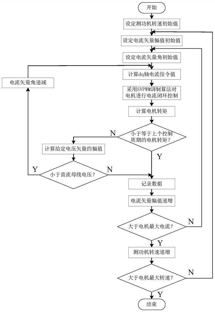
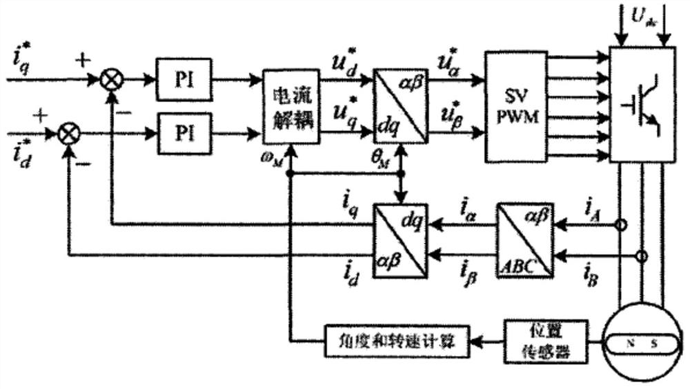
[0045] Such as Figure 1-2 As shown, the method includes the following steps:

[0046] Step 1. The dynamometer drives the calibrated permanent magnet synchronous motor to run at the set speed, calibrate the maximum torque current point of the permanent magnet synchronous motor at different speeds, and the calibrated permanent magnet synchronous motor at different speeds The optimal working point of the permanent magnet synchronous motor is not the same. It is necessary to select multiple speed points from zero speed to the maximum speed of the permanent magnet synchronous motor, record the optimal working point of the permanent magnet synchronous speed respectively, and set the initial value of the dynamometer, that is, set the first start the calibration process of the permanent magnet synchronous motor;

[0047] St...


PUM


Abstract

The present invention relates to the field of pure electric vehicle calibration test, in particular to an automatic calibration method for a permanent magnet synchronous motor, comprising the following steps: Step 1, the dynamometer drags the calibrated permanent magnet synchronous motor to run at a set speed; step 2. Record the maximum torque current point under the set current vector amplitude, i.e. the optimal operating point: step 3, the current vector amplitude increases step by step according to the preset current gradient; Reasonable planning, so that it gradually decreases from 90°, avoiding the current vector angle that is gradually increased from 0° to 90° in the existing method. When the current vector angle is above the base speed, the current vector angle is directly set to 0° and the voltage is insufficient. To adjust the size of the current problem and the problem of motor runaway.

Description

technical field [0001] The invention relates to the field of calibration testing of pure electric vehicles, in particular to an automatic calibration method for a permanent magnet synchronous motor. Background technique [0002] Compared with traditional fuel vehicles, new energy vehicles have outstanding advantages such as energy saving, environmental protection, and no pollution. The new energy vehicle industry has shown a rapid development momentum. The motor and its drive system are the core components of the new energy vehicle powertrain. The permanent magnet synchronous motor has become the first choice for domestic new energy vehicle motors due to its outstanding advantages such as high power factor, high efficiency, good control performance, and small moment of inertia. [0003] In order to give full play to the performance of the permanent magnet synchronous motor, it is necessary to calibrate the corresponding relationship between the torque and current of the moto...

Claims


Application Information

Patent Timeline
Patent Type & Authority Patents(China)
IPC IPC(8): H02P21/14H02P21/20
CPCH02P21/14H02P21/20
Inventor 李占江高超蒋元广李麟刘兵陈晨
Owner NANJING YUEBO ELECTRIC DRIVE SYST CO LTD
Learn More