
A switch control method of a driving power generation system

A technology of on-off control and generator control, applied in the direction of controlling generators, control systems, electrical components, etc., can solve problems such as insufficient power, low power generation efficiency, and power generation side cut-off

Active Publication Date: 2020-10-27
HEFEI TONGZHI ELECTRICAL CONTROL TECH
View PDF5 Cites 0 Cited by
  • Summary
  • Abstract
  • Description
  • Claims
  • Application Information

AI Technical Summary

Problems solved by technology

[0003] The system power generation process of the above-mentioned power generation system cannot be controlled, the topology is too single, there is no hot backup function, and there is a possibility of power failure
In an emergency, the power generation side cannot be cut off in time and effectively, and the adaptability to the load is poor
When the vehicle is running at low speed, the power is insufficient, and the overall power generation efficiency is low

Method used


Image

  • A switch control method of a driving power generation system
  • A switch control method of a driving power generation system
  • A switch control method of a driving power generation system

Examples


Embodiment Construction

[0043] Below, the technical solution of the present invention will be described in detail through specific examples.

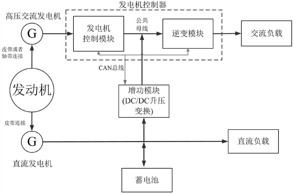
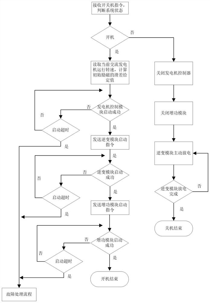
[0044] refer to figure 1 , an on-off control method of a driving power generation system proposed by the present invention, the driving power generation system includes an engine, an alternator, a DC generator, a power generation controller and a power booster module, and the power generation controller includes a generator control module and an inverter The engine is connected to the alternator and the DC generator to drive the alternator and the DC generator to rotate, the generator control module is connected to the alternator to control the operation of the alternator to output electric energy, and the input terminals of the power booster module are respectively It is connected with the DC generator and the battery, and its output terminal is connected in parallel with the output terminal of the generator control module to form a common bus as the input of...


PUM


Abstract

The invention discloses an on and off control method of a travelling power generation system. The travelling power generation system comprises an engine, an alternating current power generator, a direct current power generator, a power generation controller and a power increase module, wherein the power generation controller comprises a power generator control module and an inversion module; the engine is connected with the alternating current power generator and the direct current power generator respectively to drive the alternating current power generator and the direct current power generator to rotate; the power generator control module is connected with the alternating current power generator to control the alternating current power generator to operate and output electric energy; aninput end of the power increase module is connected with the direct current power generator and a storage battery respectively; an output end of the power increase module is connected in parallel with an output end of the power generator control module to form a common bus as an input of the inversion module; and the power generation controller is in communication connection with the power increase module by a CAN bus. A power takeoff generation system performs uniform control on the power generation controller and the power increase module; and the power generation controller and the power increase module are hot standby each other.

Description

technical field [0001] The invention relates to the technical field of driving power generation systems, in particular to a method for controlling on-off of the driving power generation system. Background technique [0002] The emergence and development of vehicle-mounted power generation power supplies have been around for a long time. Most of them are used in military combat vehicles to provide sufficient power for radar, computer and communication equipment. With the continuous advancement of power electronics technology and the automotive industry With the rapid development of assembly technology, some large civilian vehicles, such as emergency rescue vehicles, temporary communication auxiliary vehicles and even RVs, which are loaded with more electrical equipment, are equipped with vehicle-mounted power generation power systems. At present, when the power generation system is running, most of the silicon rectifier generators are driven by the belt. The inverter will boo...

Claims


Application Information

Patent Timeline
Patent Type & Authority Patents(China)
IPC IPC(8): H02P9/00H02P101/45
CPCH02P9/00H02P2101/45
Inventor 邓有飞李俊张玉章
Owner HEFEI TONGZHI ELECTRICAL CONTROL TECH
Learn More