
Polishing device for production and machining of brake camshaft

A technology for polishing devices and camshafts, which is applied in the direction of grinding drive devices, manufacturing tools, metal processing equipment, etc., can solve the problems of fixed structure of the grinding device, inability to grind and polish, unfavorable use, etc., so as to facilitate batch taking and increase practicality The effect of improving the performance and speeding up the polishing rate

Inactive Publication Date: 2019-04-12
QUANZHOU LICHENG FUHUI AUTOMOBILE PARTS CO LTD
View PDF7 Cites 1 Cited by
  • Summary
  • Abstract
  • Description
  • Claims
  • Application Information

AI Technical Summary

Problems solved by technology

[0004] Aiming at the deficiencies of the prior art, the present invention provides a polishing device for the production and processing of brake camshafts, which solves the problem that most of the polishing devices for the production and processing of brake camshafts can not be well processed after cutting during use. Both ends of the camshaft are ground and polished at the same time, thereby reducing the polishing efficiency of the camshaft, and many grinding devices are relatively fixed in structure, which is not easy to adjust according to the size of the camshaft, so that the polishing operation has certain limitations , is not conducive to the problem of using

Method used


Image

  • Polishing device for production and machining of brake camshaft
  • Polishing device for production and machining of brake camshaft
  • Polishing device for production and machining of brake camshaft

Examples


Embodiment Construction

[0030] The following will clearly and completely describe the technical solutions in the embodiments of the present invention with reference to the accompanying drawings in the embodiments of the present invention. Obviously, the described embodiments are only some, not all, embodiments of the present invention. Based on the embodiments of the present invention, all other embodiments obtained by persons of ordinary skill in the art without making creative efforts belong to the protection scope of the present invention.

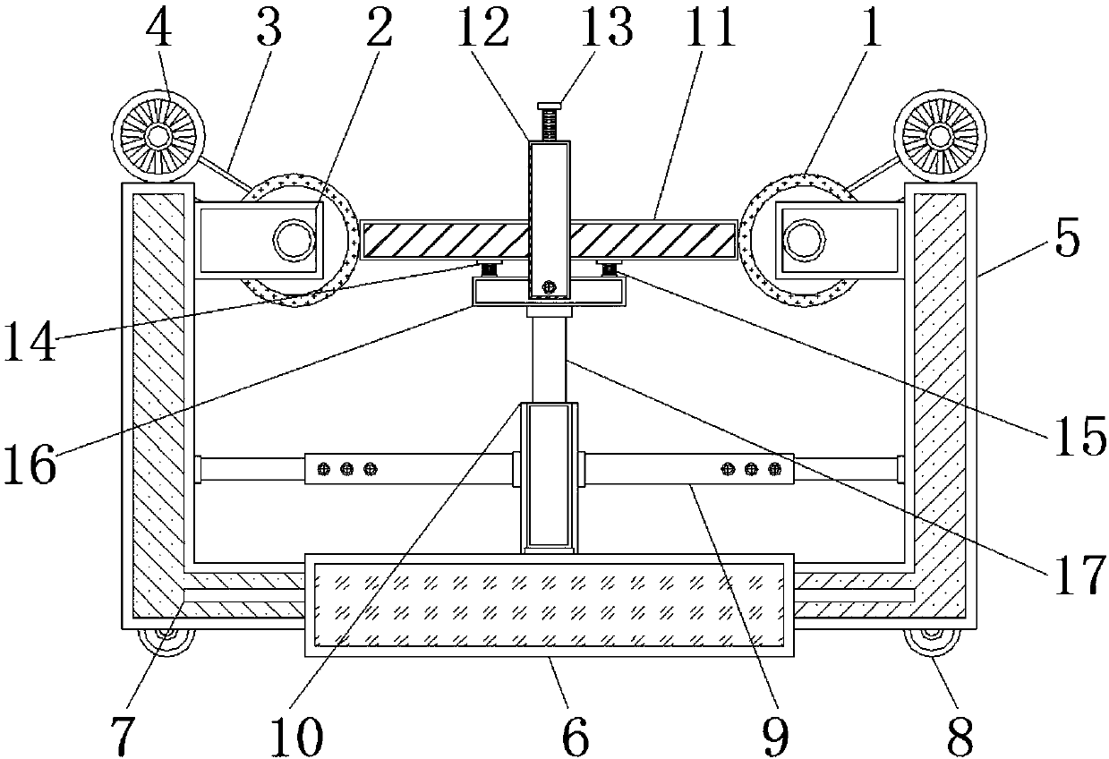
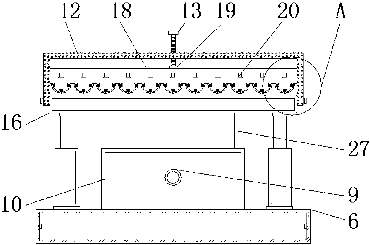
[0031] like Figure 1-8As shown, the present invention provides a technical solution: a polishing device for brake camshaft production and processing, including a polishing roller 1, a connecting block 2, a transmission belt 3, a motor 4, a side frame body 5, a base 6, a slide rail 7, a moving Wheel 8, electric telescopic column 9, fixed seat 10, camshaft body 11, placement frame 12, threaded rod 13, support plate 14, support spring 15, mounting seat 16, hydra...


PUM


Abstract

The invention discloses a polishing device for production and machining of a brake camshaft. The polishing device comprises polishing rolls, a base and a camshaft body, wherein two ends of the polishing rolls are correspondingly and rotatably connected with connecting blocks; the two sides of the inner part of the base are correspondingly interconnected with the side edges of a frame body throughsliding rails; the inner side walls of the side edges of the frame body are interconnected with one ends of electric telescopic columns; the camshaft body is arranged above the base; the lower part ofthe camshaft body is mutually attached to supporting plates; the front surface of a mounting seat is bolted to a placing frame body; a pressure plate is installed under the inner part of the placingframe body; a built-in seat is arranged under the pressure plate; and placing grooves are formed in the upper part of the built-in seat. According to the polishing device for the production and machining of the brake camshaft, by arranging the placing frame body and the mounting seat which are of detachable structures, after a batch of camshaft bodies fixed in the placing frame body are polished,the placing frame body can be taken down directly, and thus the batch taking of the camshaft bodies can be facilitated.

Description

technical field [0001] The invention relates to the technical field of brake camshaft production and processing, in particular to a polishing device for brake camshaft production and processing. Background technique [0002] The brake camshaft is mostly used in automobiles, and its shape is mostly a cylindrical structure. It is one of the key parts of the engine. The brake camshaft is mostly made of metal, which makes the camshaft have better endurance and a longer service life. Therefore, the brake The production and processing of the camshaft is also relatively fine. When the camshaft has a certain shape after processing, it needs to be cut into a corresponding length and then polished and polished. However, most brake camshafts are now used for production and processing. During the use of the polishing device, it is not possible to polish and polish both ends of the cut camshaft at the same time, thereby reducing the polishing efficiency of the camshaft, and many polishin...

Claims


Application Information

Patent Timeline
Patent Type & Authority Applications(China)
IPC IPC(8): B24B29/02B24B41/06B24B47/12
CPCB24B29/02B24B41/06B24B47/12
Inventor 许英英
Owner QUANZHOU LICHENG FUHUI AUTOMOBILE PARTS CO LTD
Learn More