Solar battery back structure design

A solar cell and backside structure technology, applied in circuits, photovoltaic power generation, electrical components, etc., can solve the problem of increasing the light-receiving area of ​​the battery, and achieve the effect of flexible and adjustable solder joint design, reduction of the front-side light-receiving area, and improvement of failure.

Pending Publication Date: 2019-04-09
SUZHOU TALESUN SOLAR TECH CO LTD
View PDF2 Cites 2 Cited by
  • Summary
  • Abstract
  • Description
  • Claims
  • Application Information

AI Technical Summary

Problems solved by technology

The back pattern of the existing cell of the shingled battery, combined with the series design of the conductive adhesive of the cell, increases the light-receiving area of ​​the cell and also increases the risk of failure of the entire string of cells due to slivers

Method used


Image

  • Solar battery back structure design
  • Solar battery back structure design
  • Solar battery back structure design

Examples


Embodiment Construction

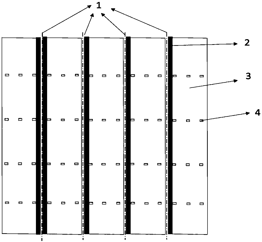
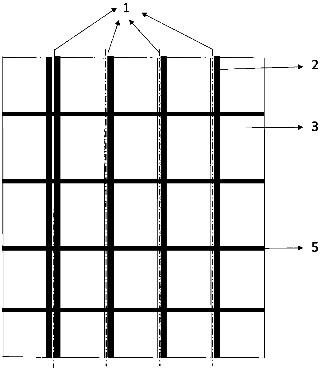
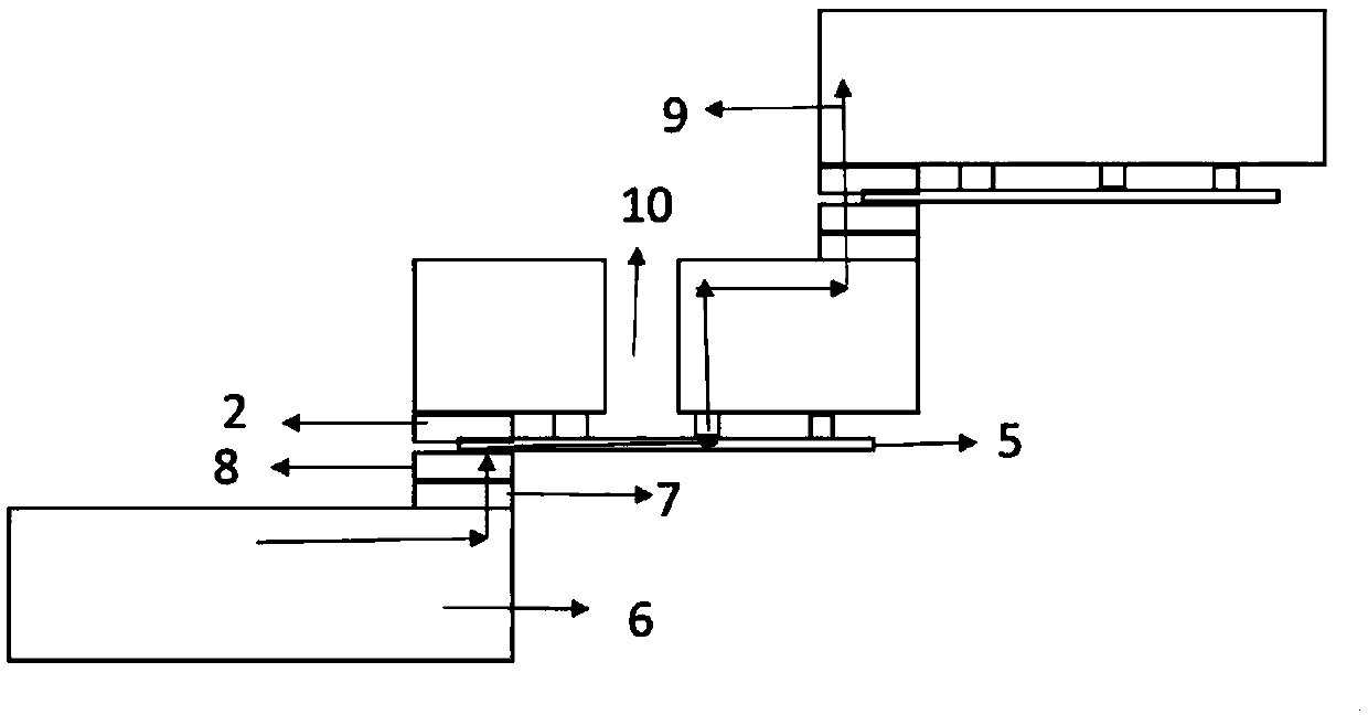
[0024] Such as Figure 1-3 As shown, a solar cell back structure design of the present invention includes a back cell 3, and the back cell 3 includes a plurality of cut cell slices 6, in order to distinguish the positions between adjacent cell slices 6 more clearly. Laser cutting marking lines 1 are marked between the adjacent battery sheets 6, vertical back electrodes 2 are provided on the left side of the battery sheet 6, and vertical positive electrodes 7 are provided on the right side of the battery sheet 6, so Conductive glue 8 is provided on the positive electrode 7 on the front side of the rear battery sheet 6 in the adjacent battery sheet 6 of the back battery 3, and the positive electrode 7 of the rear battery sheet 6 is electrically connected to the back electrode 2 of the front battery sheet 6 through the conductive glue 8. connection, the left and right shingles of adjacent battery sheets 6 are electrically connected, and the battery sheet 6 is provided with a plur...


PUM


Abstract

The invention relates to a battery back structure, and in particular relates to a solar battery back structure design. The solar battery back structure design comprises a back battery; the back battery comprises multiple battery pieces; the backs at the left sides of the battery pieces are each provided with a vertical back electrode; the fronts at the right sides of the battery pieces are each provided with a vertical positive electrode; the adjacent battery pieces are in imbricate electric connection bilaterally; multiple rows of welding spots are arranged on the battery pieces; each row ofwelding spots of the adjacent battery pieces is welded with a welding strip; conductive adhesive is arranged on the positive electrode of the battery piece; and the back and the front of the welding strip are electrically connected with the adjacent battery pieces through the conductive adhesive and the back electrode respectively. Due to a novel back welding strip pattern design, the backs of thebattery pieces are connected through a welding strip welding technology; and thus, the failure risk of the whole series of battery due to battery breakage pieces is reduced while the sufficient positive light receiving area is ensured.

Description

technical field [0001] The invention relates to a battery back structure, in particular to a solar battery back structure design. Background technique [0002] In recent years, with the development of science and technology, the market has higher and higher requirements for the output power of solar modules. Shingled modules have become one of the research hotspots of major enterprises and research institutions due to their high power output gain (20-30W). Shingled design is a component technology that increases the output power of the component by reducing the gap between the cells and increasing the number of cells. At present, the cells of shingled modules on the market use conductive adhesive to be stacked and connected in series, replacing the traditional ribbon welding and series design, which increases the light-receiving area on the front of the cells, thereby increasing the output power of the modules. The back pattern of the existing cell of the shingled battery,...

Claims


Application Information

Patent Timeline
Patent Type & Authority Applications(China)
IPC IPC(8): H01L31/05H01L31/043
CPCH01L31/043H01L31/0508Y02E10/50
Inventor 胡党平魏青竹倪志春张树德苗凤秀姚悦王金艺
Owner SUZHOU TALESUN SOLAR TECH CO LTD
Why Eureka
Try Eureka