
Convenient-to-maintain laser manufacturing device capable of reducing pollution

A manufacturing device and laser technology, applied in manufacturing tools, laser welding equipment, applications, etc., can solve the problems of high production costs, limited specifications of cutting round pipes, long assembly lines, etc., to reduce pollution, increase friction, and facilitate connection Effect

Inactive Publication Date: 2019-04-05
深圳利都科技有限公司
View PDF1 Cites 2 Cited by
  • Summary
  • Abstract
  • Description
  • Claims
  • Application Information

AI Technical Summary

Problems solved by technology

[0003] An elliptical tube laser cutting machine disclosed in Chinese utility patent application publication CN203853678U, the elliptical tube laser cutting machine, although the elliptical cutting control platform can calculate the size of the elliptical tube through the major axis and minor axis of the elliptical section of the elliptical tube , so that the rotation angle of the elliptical tube is converted into the surface perimeter and line segment of the elliptical tube, so that the elliptical tube laser cutting machine can continuously cut the elliptical tube without gaps. However, the elliptical tube laser cutting machine has the ability to cut round tubes The fixed single performance makes the specifications of cutting round pipes limited, the production cost is high, and the assembly line is longer

Method used


Image

  • Convenient-to-maintain laser manufacturing device capable of reducing pollution
  • Convenient-to-maintain laser manufacturing device capable of reducing pollution
  • Convenient-to-maintain laser manufacturing device capable of reducing pollution

Examples


Embodiment Construction

[0029] The following will clearly and completely describe the technical solutions in the embodiments of the present invention with reference to the accompanying drawings in the embodiments of the present invention. Obviously, the described embodiments are only some, not all, embodiments of the present invention.

[0030] In the description of the present invention, unless otherwise stated, the meaning of "plurality" is two or more; the terms "upper", "lower", "left", "right", "inner", "outer" , "front end", "rear end", "head", "tail", etc. indicate the orientation or positional relationship based on the orientation or positional relationship shown in the drawings, and are only for the convenience of describing the present invention and simplifying the description, rather than Nothing indicating or implying that a referenced device or element must have a particular orientation, be constructed, and operate in a particular orientation should therefore not be construed as limiting ...


PUM


Abstract

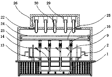
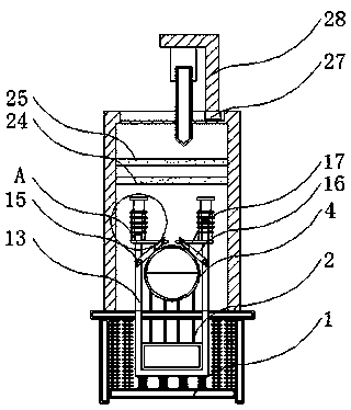
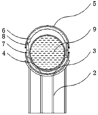
The invention discloses a convenient-to-maintain laser manufacturing device capable of reducing pollution and relates to the technical field of round pipe manufacturing. The convenient-to-maintain laser manufacturing device capable of reducing the pollution specifically comprises to a workbench and connecting rods, a first placing strip is fixedly welded to the upper end of the workbench, guide plates are arranged on the outer walls of the tops of vertical rods, the connecting rods are fixedly welded to the two sides of the upper end of the workbench, mounting blocks are fixedly welded to theinner walls of the connecting rods, reflection plates and focusing plates are arranged on the inner walls of the mounting blocks, the focusing plates are arranged below the reflection plates, slidingchutes are formed in the edges of the tops of the connecting rods, sliding blocks are arranged inside the sliding chutes, and a movable frame is fixedly welded to the tops of the sliding blocks. According to the convenient-to-maintain laser manufacturing device capable of reducing the pollution, a curved surface of a covering ring and a curved surface of a mounting ring are arranged in a matched mode, the fixing effects are achieved on the head end and the tail end of a to-be-cut round pipe, and the arrangement that the curved surfaces are attached to each other can be used to rotate the to-be-cut round pipe in the process of cutting the round pipe.

Description

technical field [0001] The invention relates to the technical field related to circular tube manufacturing, in particular to a laser manufacturing device that can reduce pollution and is easy to maintain. Background technique [0002] Round pipe refers to the steel that is open at both ends and has a hollow concentric section. The ratio of its length to the surrounding area is large. Specifications are represented by external dimensions, inner diameter and wall thickness, and its size ranges from a small capillary tube to a large round steel tube with a diameter of several meters. The round tube can be used in pipelines, thermal equipment, machinery industry, petroleum geological drilling, containers , chemical industry and special purposes, so round pipes play an extremely important role in the modern construction industry, so the production of round pipes is particularly important, especially for the cutting of round pipes. In the process of cutting modern round pipes, las...

Claims


Application Information

Patent Timeline
Patent Type & Authority Applications(China)
IPC IPC(8): B23K26/38B23K26/08B23K26/70B23K101/06
CPCB23K26/38B23K26/0823B23K26/702
Inventor 邱子杰
Owner 深圳利都科技有限公司
Learn More