
A method and system for detecting that flow rate of high-temperature molten fluid

A fluid velocity, high temperature melting technology, applied in liquid/fluid solid measurement, measurement flow/mass flow, measurement capacity, etc., can solve the problem of low detection accuracy of molten fluid flow velocity

Active Publication Date: 2019-03-29
CENT SOUTH UNIV
View PDF10 Cites 11 Cited by
  • Summary
  • Abstract
  • Description
  • Claims
  • Application Information

AI Technical Summary

Problems solved by technology

[0006] The method and system for detecting the flow velocity of high-temperature molten fluid provided by the present invention solve the existing technical problem that the detection accuracy of the flow velocity of molten fluid with high temperature, high speed, and high light is not high

Method used


Image

  • A method and system for detecting that flow rate of high-temperature molten fluid
  • A method and system for detecting that flow rate of high-temperature molten fluid
  • A method and system for detecting that flow rate of high-temperature molten fluid

Examples


Embodiment 1

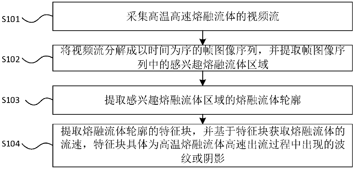
[0088] refer to figure 1 , the method for detecting the flow rate of a high-temperature molten fluid provided in Embodiment 1 of the present invention includes:

[0089] Step S101, collecting video streams of high-temperature and high-speed molten fluid;

[0090] Step S102, decomposing the video stream into time-ordered frame image sequences, and extracting the molten fluid region of interest in the frame image sequences;

[0091] Step S103, extracting the molten fluid profile of the molten fluid region of interest;

[0092] Step S104, extracting feature blocks of the outline of the molten fluid, and obtaining the flow velocity of the molten fluid based on the feature blocks, specifically, the feature blocks are ripples or shadows that appear during the high-speed outflow of the high-temperature molten fluid.

[0093] The method for detecting the flow velocity of the high-temperature molten fluid provided by the embodiment of the present invention collects the video stream o...

Embodiment 2

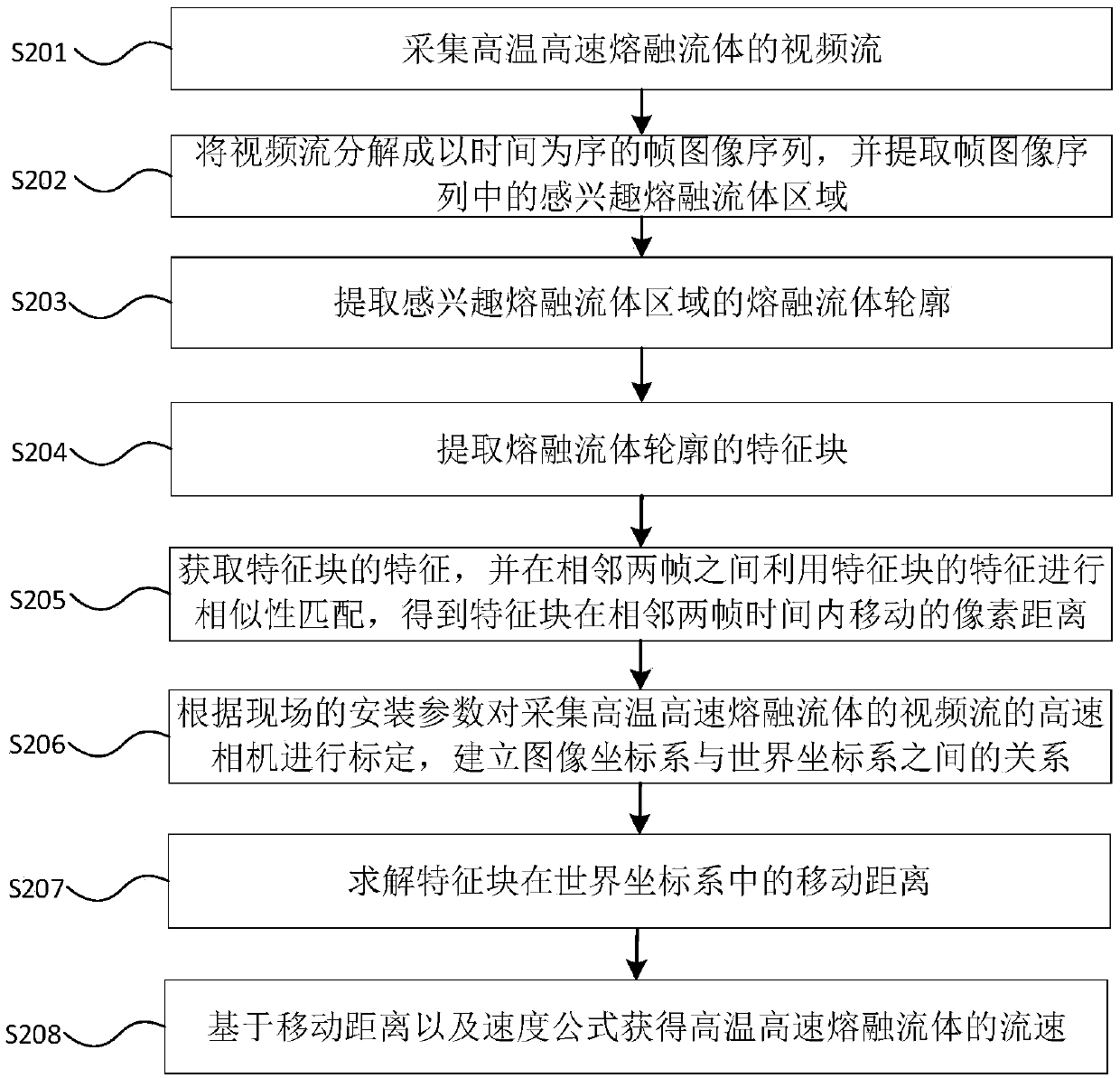
[0096] refer to figure 2 , the method for detecting the flow rate of a high-temperature molten fluid provided in Embodiment 2 of the present invention, comprising:

[0097] Step S201, collecting video streams of high-temperature and high-speed molten fluid.

[0098] Specifically, in the embodiment of the present invention, a video stream of high-temperature and high-speed melting fluid is collected by a high-speed camera.

[0099] Step S202, decomposing the video stream into time-ordered frame image sequences, and extracting the molten fluid region of interest in the frame image sequences.

[0100] Specifically, in this embodiment, after the video stream information of the high-temperature and high-speed melting fluid object is collected by a high-speed camera; Fluid region; then, image enhancement operation is performed on the region of interest and the contour of the molten fluid feature block is extracted by a single-pixel contour extraction module to obtain a binary fra...


PUM


Abstract

A method and system for detect that flow rate of high-temperature molten fluid are disclosed. The method includes: capturing a video stream of high temperature and high speed molten fluid, decomposingthe video stream into a sequence of frame images in chronological order, and extracting the region of the melt fluid of interest in the frame image sequence, extracting a melt fluid profile of that region of the melt fluid of inter, extracting a feature block of the molten fluid profile, and obtaining a flow rate of the molten fluid based on the feature block. The invention solves the problem that the prior art pairs with high temperature, In order to detect the velocity of molten fluid with high temperature, high speed and high luminosity, the high frame rate video stream is obtained by non-invasive method, and the small target salient feature blocks on the molten fluid are tracked and located accurately in real-time, so that the velocity of molten fluid with high temperature, high speedand high luminosity is detected. The method and the system have the advantages of high accuracy, strong stability, long periodicity, being suitable for high-temperature or over-high-temperature high-speed flowing fluids, low investment cost and the like.

Description

technical field [0001] The invention mainly relates to the technical field of high-temperature molten fluid flow velocity detection, in particular to a high-temperature molten fluid flow velocity detection method and system. Background technique [0002] In the metallurgical industry, ferrous metals and non-ferrous metals are mostly extracted from ores or concentrates by pyrometallurgy under high temperature conditions, and crude metals or metal concentrates and slags in molten state are produced from high-temperature closed reaction furnaces. High-speed outflow, such as molten iron flowing out of the blast furnace taphole in the iron and steel industry process, matte out of the reverberatory furnace in the pyrometallurgical copper smelting process, crude zinc out of the smelting furnace in the pyrometallurgy process of zinc smelting, etc. The change trend of the pressure in the reaction furnace is an important indicator to characterize whether the reaction furnace is runnin...

Claims


Application Information

Patent Timeline
Patent Type & Authority Applications(China)
IPC IPC(8): G06K9/00G06K9/32G06K9/46G06K9/62G06T7/507G06T7/73G01F1/7086G06V10/25G06V10/42G06V10/44
CPCG06T7/507G06T7/73G06V20/40G06V10/25G06V10/44G01F1/7086G06F18/22G01F1/712G06T7/248G01F25/10G06V10/42Y02P10/20G06T7/80G01F15/00G06T2207/10016G06V20/49
Inventor 蒋朝辉何磊陈致蓬桂卫华潘冬阳春华谢永芳张海峰
Owner CENT SOUTH UNIV
Learn More