
Resource recycling process and system for high-temperature plasma of chlorine-containing waste

A plasma and resource recovery technology, applied in the field of plasma resource recovery process and system, can solve the problems of increased waste treatment cost, large amount of fly ash, large consumption of deacidification agent, etc., to achieve resource recovery and utilization, heat High recovery efficiency and low operating cost

Inactive Publication Date: 2019-03-29
SHANDONG BO RUN IND TECH
View PDF0 Cites 13 Cited by
  • Summary
  • Abstract
  • Description
  • Claims
  • Application Information

AI Technical Summary

Problems solved by technology

[0013] 1) Unable to treat high chlorine solid waste, liquid waste and gas waste at the same time
[0014] 2) High chlorine-containing organic waste cannot be completely incinerated, and hazardous waste such as slag and fly ash will be generated, and secondary treatment is required; and the incineration temperature is low, and highly toxic substances such as dioxin and furan will be produced
[0015] 3) In the traditional acid gas HCl removal process, the consumption of deacidification agent is large, the cost of the agent is high, and the generation of solid waste and waste liquid increases the cost of waste treatment
[0016] 4) The traditional incineration process has a large amount of flue gas, low HCl content in the flue gas, and a large amount of fly ash, resulting in poor HCl absorption effect, low concentration of hydrochloric acid (about 10%), and high impurity content, which cannot be directly used or sold

Method used


Image

  • Resource recycling process and system for high-temperature plasma of chlorine-containing waste

Examples


Embodiment

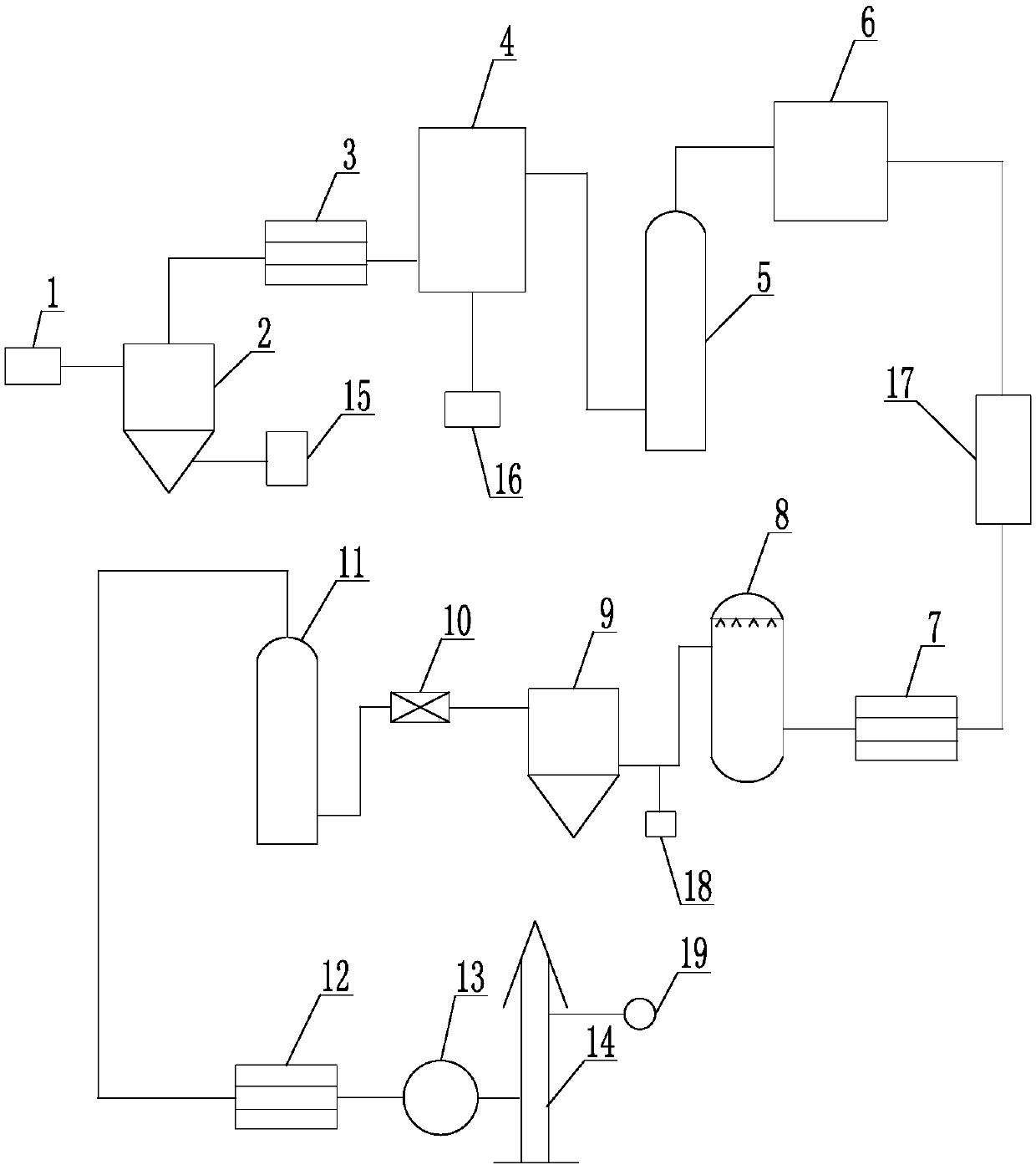
[0063] Such as figure 1 As shown, the system used in the high-temperature plasma recycling process of chlorine-containing wastes includes a sequentially connected feed system 1, plasma gasification furnace 2, primary waste heat exchanger 3, acid absorption system 4, alkali washing Tower 5, secondary combustion chamber 6, secondary waste heat exchanger 7, quench cooler 8, bag filter 9, flue heater 10, SCR catalytic tower 11, heat exchanger 12, induced draft fan 13 and chimney 14.

[0064] The slag outlet of the plasma gasification furnace 2 is also connected with a cooling device 15 .

[0065] The acid absorption system 4 is a circulating water absorption system, and the acid absorption system 4 is also connected with an acid filtering device 16 .

[0066] The rear flue of the second combustion chamber 6 is provided with an SNCR denitrification device 17 .

[0067] Activated carbon and sodium bicarbonate injection device 18 are arranged on the pipeline between quench cooler 8...


PUM


Abstract

The invention belongs to the technical field of industrial waste treatment, and particularly relates to a resource recycling process and system for high-temperature plasma of chlorine-containing waste. The method comprises the steps that (1) the chlorine-containing waste is conveyed into a plasma gasifier through a feeding system; (2) synthesis gas produced through splitting decomposition is cooled by a first-stage waste heat exchanger; (3) after entering an acid absorption system to absorb acid, the synthesis gas enters an alkaline tower to be further deacidified; (4) the deacidified synthesis gas enters a secondary combustion chamber to be combusted, and generated high-temperature flue gas is cooled by a second-stage waste heat exchanger; (5) after the cooled flue gas enters a quench cooler to be subjected to quenching, the flue gas enters a bag-type dust remover for dust removal; (6) the flue gas with dust removed enters a flue heater to be warmed; (7) the flue gas enters an SCR catalytic tower to remove nitric oxide in the flue gas; and (8) after the flue gas subjected to SCR treatment enters the heat exchanger for heat exchange, the flue gas is drawn out by an induced draft fan, and the flue gas is discharged into the atmosphere through a chimney. By means of the resource recycling process and system, resource, harmless, reducing and stabilizing treatment of the chlorine-containing waste is achieved, and the system operation cost is low.

Description

technical field [0001] The invention belongs to the technical field of industrial waste treatment, and in particular relates to a high-temperature plasma resource recycling process and system for chlorine-containing waste. Background technique [0002] Existing chemical, pharmaceutical, pesticide and other industrial industries produce a large amount of highly chlorine-containing waste, the main organic components are chlorinated alkanes, chlorinated olefins, chlorinated benzene series, etc. These organic wastes are hazardous wastes, and if no treatment measures are taken, they will be directly Landfill or discharge will cause serious damage to the atmosphere, soil and water resources, threatening the environment on which human beings depend. Now basically adopt solidification method, landfill method or incineration method to deal with. The main processing methods are as follows: [0003] 1. Solidification method: stabilization / solidification technology, that is, hazardous...

Claims


Application Information

Patent Timeline
Patent Type & Authority Applications(China)
IPC IPC(8): F23G5/08F23G5/027F23G5/16F23G5/46F23J15/02F23J15/06F23J15/08B01D46/02B01D53/34B01D53/50B01D53/56B01D53/68B01D53/72B01D53/78B01D53/79B01D53/86
CPCB01D46/023B01D53/343B01D53/50B01D53/56B01D53/68B01D53/72B01D53/78B01D53/79B01D53/8625F23G5/0276F23G5/085F23G5/16F23G5/46F23G2201/60F23J15/02F23J15/022F23J15/06F23J15/08F23J2215/10F23J2217/101Y02E20/30
Inventor 谢新兵陈兵
Owner SHANDONG BO RUN IND TECH
Learn More