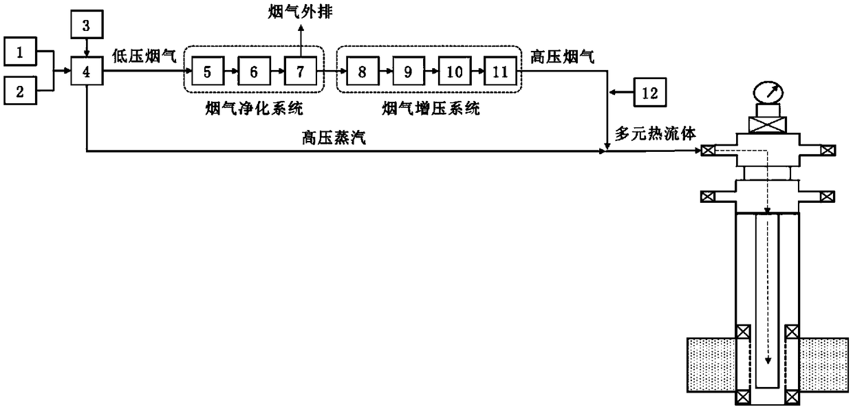
Technology and system for producing multi-component thermal fluid in ocean platform

A multi-thermal fluid and offshore platform technology, applied in the oil field, can solve the problems of restricting the large-scale thermal recovery development of offshore heavy oil oilfields, the high-pressure supply system occupies a large area, and the waste water treatment system is increased, so as to reduce the risk of gas channeling and reduce the risk of gas channeling. The effect of small equipment investment and reduced placement area

Inactive Publication Date: 2019-03-15
CHINA NAT OFFSHORE OIL CORP +1
View PDF6 Cites 0 Cited by
  • Summary
  • Abstract
  • Description
  • Claims
  • Application Information

AI Technical Summary

Problems solved by technology

[0004] Due to the small space of the offshore platform and the shortage of fresh water and power resources, the above multi-element thermal fluid generation processes cannot solve the problems of large footprint, high energy consumption, and high heat enthalpy of air, oxygen-enriched air or nitrogen high-pressure supply systems. The low water vapor injection rate seriously restricts the large-scale thermal recovery development process of offshore heavy oil fields
In addition, the existing multi-component thermal fluid generation process cannot avoid the problem of air pollution caused by the exhaust gas containing sulfur dioxide, nitrogen oxides, dust and other components generated by the combustion of small steam boilers. If the conventional flue gas desulfurization and denitrification process is adopted, it is inevitable To generate waste water containing a large amount of soot, oil, heavy metals, etc., it is necessary to increase the waste water treatment system, the cost and energy consumption will increase, and the volume is large, so it is not suitable to be installed on the offshore platform

Method used


Image

  • Technology and system for producing multi-component thermal fluid in ocean platform

Examples


Embodiment

[0046] The application will be described in further detail below in conjunction with the accompanying drawings, so that those skilled in the art can practice the application. It is to be understood that other embodiments may be utilized, and that appropriate changes may be made without departing from the spirit or scope of the application. To avoid detail not necessary to enable those skilled in the art to practice the application, the description may omit certain information known to those skilled in the art. Accordingly, the following detailed description should not be read in a limiting sense, and the scope of the present application is defined only by the appended claims.

[0047] The general principle of the application is explained below with regard to thermal recovery wells of a heavy oil reservoir on an offshore oil production platform in Bohai Bay as an example, but it should be noted that the application is by no means limited to thermal recovery wells of heavy oil r...


PUM


Abstract

The invention discloses a technology for producing multi-component thermal fluid in an ocean platform. The technology comprises steps as follows: air and crude oil are supercharged and injected into afuel oil steam boiler; the supercharged crude oil is burnt in the fuel oil steam boiler, exhaust gas is produced, heat is released, and steam is produced; the produced exhaust gas is subjected to dust removing, desulfuration and denitration treatment; the treated exhaust gas is dehydrated, filtered and supercharged, and a corrosion inhibitor is injected into the supercharged exhaust gas; the produced steam is mixed with the supercharged exhaust gas, and the multi-component thermal fluid with an adjustable gas-liquid ratio is obtained. The invention further discloses a system for implementingthe technology. The system comprises an air compression device, a crude oil supply device, a water supply device, the fuel oil steam boiler, an exhaust gas purification device, an exhaust gas supercharging device and a chemical injection device. The multi-component thermal fluid with the adjustable gas-liquid ratio meets demands of different types of oil reservoirs; the problems that an existing system occupies a large area and is higher in energy consumption are solved.

Description

technical field [0001] The present application relates to but not limited to the petroleum field, and particularly relates to but not limited to a process and a system for producing an environment-friendly mixed multi-component thermal fluid in an offshore platform. Background technique [0002] Multivariate thermal fluid is a kind of water vapor, N 2 , CO 2 And other components, high temperature fluid used for enhanced recovery in heavy oil fields. Since 2008, the multiple thermal fluid thermal recovery technology has been successfully implemented on offshore platforms for more than 30 well times, and the production capacity of single well thermal recovery is 2 to 3 times higher than that of cold recovery, providing technical support for the efficient development of offshore heavy oil fields. [0003] Existing multi-element thermal fluid production process (referring to Chinese patent CN1804366A) utilizes the combustion injection mechanism of aerospace rocket engine, fuel...

Claims


Application Information

Patent Timeline
Patent Type & Authority Applications(China)
IPC IPC(8): B01D53/50B01D53/78F25D17/02
CPCB01D53/228B01D53/50B01D53/78F25D17/02B01D2258/0283
Inventor 孙永涛刘义刚张卫行孙玉豹邹剑林珊珊梅伟姬辉
Owner CHINA NAT OFFSHORE OIL CORP
Why Eureka
Try Eureka